Interplanetary Overlay Network (ION) Design and Operation's Guide
Version 4.1.3 JPL D-48259
Document Change Log
| Ver No. | Date | Description | Note |
|---|---|---|---|
| V4.1.3 | 12/08 /2023 | converted to MarkDown | |
| V4.0.1 | 11/20/2020 | ION 4.0.1 | |
| V3.6.2 | 11/19/2018 | ION 3.6.2 release features | Skipped V3.6.1. |
| V3.6 | 12/31/2017 | ION 3.6 release features | Skipped V3.5. |
| V3.4 | 3/28/2016 | ION 3.4 release features | |
| V3.3 | 3/4/2015 | ION 3.3 release features | |
| V3.2 | 12/17/2013 | ION 3.2 release features | |
| V3.1 | 9/28/2012 | ION 3.1 release features | |
| V3.0 | 3/22/2012 | Align with ION 3.0 release | |
| V1.13 | 10/13/2011 | Updates for Source Forge Release | |
| V1.12 | 6/11/2010 | Updates for second open source release (2.2) | |
| V1.11 | 12/11/2009 | BRS updates, multi-node config | |
| V1.10 | 10/23/2009 | Final additions prior to DINET 2 experiment | |
| V1.9 | 6/29/2009 | Add updates for DINET 2, including CFDP, ionsec | |
| V1.8 | 2/6/2009 | Update discussion of Contact Graph Routing; document status msg formats | |
| V1.7 | 12/1/2008 | Add documentation for OWLT simulator, BP extension | |
| V1.6 | 10/03/2008 | Add documentation of sm_SemUnend | |
| V1.5 | 09/20/2008 | Revisions requested SQA | |
| V1.4 | 07/31/2008 | Add a section on optimizing ION-based network; tuning | |
| V1.3 | 07/08/2008 | Revised some details of CGR | |
| V1.2 | 05/24/2008 | Revised man pages for bptrace, ltprc, bprc. | |
| V1.1 | 05/18/2008 | Some additional diagrams | |
| V1.0 | 04/28/2008 | Initial version of ION design and ops manual |
Design
The Interplanetary Overlay Network (ION) software distribution is an implementation of Delay-Tolerant Networking (DTN) architecture as described in Internet RFC 4838. It is designed to enable inexpensive insertion of DTN functionality into embedded systems such as robotic spacecraft. The intent of ION deployment in space flight mission systems is to reduce cost and risk in mission communications by simplifying the construction and operation of automated digital data communication networks spanning space links, planetary surface links, and terrestrial links.
A comprehensive overview of DTN is beyond the scope of this document. Very briefly, though, DTN is a digital communication networking technology that enables data to be conveyed between two communicating entities automatically and reliably even if one or more of the network links in the end-to-end path between those entities is subject to very long signal propagation latency and/or prolonged intervals of unavailability.
The DTN architecture is much like the architecture of the Internet, except that it is one layer higher in the familiar ISO protocol "stack". The DTN analog to the Internet Protocol (IP), called "Bundle Protocol" (BP), is designed to function as an "overlay" network protocol that interconnects "internets" -- including both Internet-structured networks and also data paths that utilize only space communication links as defined by the Consultative Committee for Space Data Systems (CCSDS) -- in much the same way that IP interconnects "subnets" such as those built on Ethernet, SONET, etc. By implementing the DTN architecture, ION provides communication software configured as a protocol stack that looks like this:
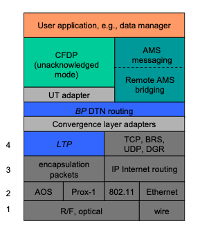
Figure 1 DTN protocol stack
Data traversing a DTN are conveyed in DTN bundles -- which are functionally analogous to IP packets -- between BP endpoints which are functionally analogous to sockets. Multiple BP endpoints may be accessed at a single DTN node -- functionally analogous to a network interface card -- and multiple nodes may reside on the same computer just as a single computer (host or router) in the Internet may have multiple network interface cards.
BP endpoints are identified by Universal Record Identifiers (URIs), which are ASCII text strings of the general form:
scheme_name:scheme_specific_part
For example:
dtn://topquark.caltech.edu/mail
But for space flight communications this general textual representation might impose more transmission overhead than missions can afford. For this reason, ION is optimized for networks of endpoints whose IDs conform more narrowly to the following scheme:
ipn:node_number.service_number
This enables them to be abbreviated to pairs of unsigned binary integers via a technique called Compressed Bundle Header Encoding (CBHE). CBHE-conformant BP endpoint IDs (EIDs) are not only functionally similar to Internet socket addresses but also structurally similar: node numbers are roughly analogous to Internet node numbers (IP addresses), in that they typically identify the flight or ground data system computers on which network software executes, and service numbers are roughly analogous to TCP and UDP port numbers.
More generally, the node numbers in CBHE-conformant BP endpoint IDs are one manifestation of the fundamental ION notion of network node number: in the ION architecture there is a natural one-to-one mapping not only between node numbers and BP endpoint node numbers but also between node numbers and:
- LTP engine IDs
- AMS continuum numbers
- CFDP entity numbers
Starting with version 3.1 of ION, this endpoint naming rule is experimentally extended to accommodate bundle multicast, i.e., the delivery of copies of a single transmitted bundle to multiple nodes at which interest in that bundle's payload has been expressed. Multicast in ION -- "Interplanetary Multicast" (IMC) -- is accomplished by simply issuing a bundle whose destination endpoint ID conforms to the following scheme:
imc:group_number.service_number
A copy of the bundle will automatically be delivered at every node that has registered in the destination endpoint.
(Note: for now, the operational significance of a given group number must be privately negotiated among ION users. If this multicast mechanism proves useful, IANA may at some point establish a registry for IMC group numbers. Also note that a new mechanism for bundle multicast is introduced in ION 4.0.1, along with support for Bundle Protocol version 7. This new mechanism vastly simplifies bundle multicast; chiefly, the imcadmin utility is deprecated.)
Structure and function
The ION distribution comprises the following software packages:
- ici (Interplanetary Communication Infrastructure), a set of general-purpose libraries providing common functionality to the other packages. The ici package includes a security policy component that supports the implementation of security mechanisms at multiple layers of the protocol stack.
- ltp (Licklider Transmission Protocol), a core DTN protocol that provides transmission reliability based on delay-tolerant acknowledgments, timeouts, and retransmissions. The LTP specification is defined in Internet RFC 5326.
- bp (Bundle Protocol), a core DTN protocol that provides delay-tolerant forwarding of data through a network in which continuous end-to-end connectivity is never assured, including support for delay-tolerant dynamic routing. The BP specification is defined in Internet RFC 5050.
- dgr (Datagram Retransmission), an alternative implementation of LTP that is designed for use on the Internet. Equipped with algorithms for TCP-like congestion control, DGR enables data to be transmitted via UDP with reliability comparable to that provided by TCP. The dgr system is provided primarily for the conveyance of Meta-AMS (see below) protocol traffic in an Internet-like environment.
-
ams (Asynchronous Message Service), an application-layer service that is not part of the DTN architecture but utilizes underlying DTN protocols. AMS comprises three protocols supporting the distribution of brief messages within a network:
-
The core AAMS (Application AMS) protocol, which does message distribution on both the publish/subscribe model and the client/server model, as required by the application.
- The MAMS (Meta-AMS) protocol, which distributes control information enabling the operation of the Application AMS protocol.
- The RAMS (Remote AMS) protocol, which performs aggregated message distribution to end nodes that may be numerous and/or accessible only over very expensive links, using an aggregation tree structure similar to the distribution trees used by Internet multicast technologies.
- cfdp (CCSDS File Delivery Protocol), another application-layer service that is not part of the DTN architecture but utilizes underlying DTN protocols. CFDP performs the segmentation, transmission, reception, reassembly, and delivery of files in a delay-tolerant manner. ION's implementation of CFDP conforms to the "class 1" definition of the protocol in the CFDP standard, utilizing DTN (BP, nominally over LTP) as its "unitdata transport" layer.
- bss (Bundle Streaming Service), a system for efficient data streaming over a delay-tolerant network. The bss package includes (a) a convergence-layer protocol (bssp) that preserves in-order arrival of all data that were never lost en route, yet ensures that all data arrive at the destination eventually, and (b) a library for building delay-tolerant streaming applications, which enables low-latency presentation of streamed data received in real time while offering rewind/playback capability for the entire stream including late-arriving retransmitted data.
- tc (Trusted Collective), a system for propagating critical yet non-confidential information in a trustworthy manner. tc can be thought of as a delay-tolerant functional analog to the servers in client/server architectures. Multiple applications may make use of the tc system, but currently only one tc application is bundled with ION: dtka (delay-tolerant key administration), which provides delay-tolerant public key infrastructure.
Taken together, the packages included in the ION software distribution constitute a communication capability characterized by the following operational features:
- Reliable conveyance of data over a delay-tolerant network (dtnet), i.e., a network in which it might never be possible for any node to have reliable information about the detailed current state of any other node.
- Built on this capability, reliable data streaming, reliable file delivery, and reliable distribution of short messages to multiple recipients (subscribers) residing in such a network.
-
Management of traffic through such a network, taking into consideration:
-
requirements for data security
- scheduled times and durations of communication opportunities
- fluctuating limits on data storage and transmission resources
- data rate asymmetry
- the sizes of application data units
- and user-specified final destination, priority, and useful lifetime for those data units.
- Facilities for monitoring the performance of the network.
- Robustness against node failure.
- Portability across heterogeneous computing platforms.
- High speed with low overhead.
- Easy integration with heterogeneous underlying communication infrastructure, ranging from Internet to dedicated spacecraft communication links.
Constraints on the Design
A DTN implementation intended to function in an interplanetary network environment -- specifically, aboard interplanetary research spacecraft separated from Earth and from one another by vast distances -- must operate successfully within two general classes of design constraints: link constraints and processor constraints.
- Link constraints
All communications among interplanetary spacecraft are, obviously, wireless. Less obviously, those wireless links are generally slow and are usually asymmetric.
The electrical power provided to on-board radios is limited and antennae are relatively small, so signals are weak. This limits the speed at which data can be transmitted intelligibly from an interplanetary spacecraft to Earth, usually to some rate on the order of 256 Kbps to 6 Mbps.
The electrical power provided to transmitters on Earth is certainly much greater, but the sensitivity of receivers on spacecraft is again constrained by limited power and antenna mass allowances. Because historically the volume of command traffic that had to be sent to spacecraft was far less than the volume of telemetry the spacecraft were expected to return, spacecraft receivers have historically been engineered for even lower data rates from Earth to the spacecraft, on the order of 1 to 2 Kbps.
As a result, the cost per octet of data transmission or reception is high and the links are heavily subscribed. Economical use of transmission and reception opportunities is therefore important, and transmission is designed to enable useful information to be obtained from brief communication opportunities: units of transmission are typically small, and the immediate delivery of even a small part (carefully delimited) of a large data object may be preferable to deferring delivery of the entire object until all parts have been acquired.
- Processor constraints
The computing capability aboard a robotic interplanetary spacecraft is typically quite different from that provided by an engineering workstation on Earth. In part this is due, again, to the limited available electrical power and limited mass allowance within which a flight computer must operate. But these factors are exacerbated by the often intense radiation environment of deep space. In order to minimize errors in computation and storage, flight processors must be radiation-hardened and both dynamic memory and non-volatile storage (typically flash memory) must be radiation-tolerant. The additional engineering required for these adaptations takes time and is not inexpensive, and the market for radiation-hardened spacecraft computers is relatively small; for these reasons, the latest advances in processing technology are typically not available for use on interplanetary spacecraft, so flight computers are invariably slower than their Earth-bound counterparts. As a result, the cost per processing cycle is high and processors are heavily subscribed; economical use of processing resources is very important.
The nature of interplanetary spacecraft operations imposes a further constraint. These spacecraft are wholly robotic and are far beyond the reach of mission technicians; hands-on repairs are out of the question. Therefore the processing performed by the flight computer must be highly reliable, which in turn generally means that it must be highly predictable. Flight software is typically required to meet "hard" real-time processing deadlines, for which purpose it must be run within a hard real-time operating system (RTOS).
One other implication of the requirement for high reliability in flight software is that the dynamic allocation of system memory may be prohibited except in certain well-understood states, such as at system start-up. Unrestrained dynamic allocation of system memory introduces a degree of unpredictability into the overall flight system that can threaten the reliability of the computing environment and jeopardize the health of the vehicle.
Design Principles
The design of the ION software distribution reflects several core principles that are intended to address these constraints.
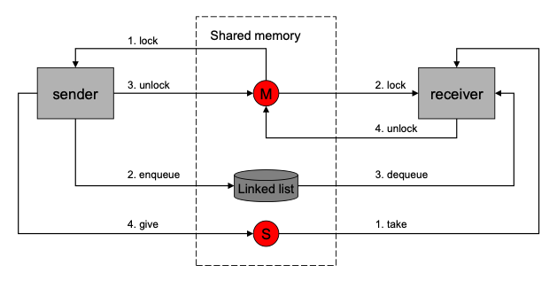
Figure 2 ION inter-task communication
- Shared memory
Since ION must run on flight processors, it had to be designed to function successfully within an RTOS. Many real-time operating systems improve processing determinism by omitting the support for protected-memory models that is provided by Unix-like operating systems: all tasks have direct access to all regions of system memory. (In effect, all tasks operate in kernel mode rather than in user mode.) ION therefore had to be designed with no expectation of memory protection.
But universally shared access to all memory can be viewed not only as a hazard but also as an opportunity. Placing a data object in shared memory is an extremely efficient means of passing data from one software task to another.
ION is designed to exploit this opportunity as fully as possible. In particular, virtually all inter-task data interchange in ION follows the model shown in Figure 2:
- The sending task takes a mutual exclusion semaphore (mutex) protecting a linked list in shared memory (either DRAM or non-volatile memory), appends a data item to the list, releases the mutex, and gives a "signal" semaphore associated with the list to announce that the list is now non-empty.
- The receiving task, which is already pending on the linked list's associated signal semaphore, resumes execution when the semaphore is given. It takes the associated mutex, extracts the next data item from the list, releases the mutex, and proceeds to operate on the data item from the sending task.
Semaphore operations are typically extremely fast, as is the storage and retrieval of data in memory, so this inter-task data interchange model is suitably efficient for flight software.
- Zero-copy procedures
Given ION's orientation toward the shared memory model, a further strategy for processing efficiency offers itself: if the data item appended to a linked list is merely a pointer to a large data object, rather than a copy, then we can further reduce processing overhead by eliminating the cost of byte-for-byte copying of large objects.
Moreover, in the event that multiple software elements need to access the same large object at the same time, we can provide each such software element with a pointer to the object rather than its own copy (maintaining a count of references to assure that the object is not destroyed until all elements have relinquished their pointers). This serves to reduce somewhat the amount of memory needed for ION operations.
- Highly distributed processing
The efficiency of inter-task communications based on shared memory makes it practical to distribute ION processing among multiple relatively simple pipelined tasks rather than localize it in a single, somewhat more complex daemon. This strategy has a number of advantages:
- The simplicity of each task reduces the sizes of the software modules, making them easier to understand and maintain, and thus it can somewhat reduce the incidence of errors.
- The scope of the ION operating stack can be adjusted incrementally at run time, by spawning or terminating instances of configurable software elements, without increasing the size or complexity of any single task and without requiring that the stack as a whole be halted and restarted in a new configuration. In theory, a module could even be upgraded with new functionality and integrated into the stack without interrupting operations.
-
The clear interfaces between tasks simplify the implementation of flow control measures to prevent uncontrolled resource consumption.
-
Portability
Designs based on these kinds of principles are foreign to many software developers, who may be far more comfortable in development environments supported by protected memory. It is typically much easier, for example, to develop software in a Linux environment than in VxWorks 5.4. However, the Linux environment is not the only one in which ION software must ultimately run.
Consequently, ION has been designed for easy portability. POSIX™ API functions are widely used, and differences in operating system support that are not concealed within the POSIX abstractions are mostly encapsulated in two small modules of platform-sensitive ION code. The bulk of the ION software runs, without any source code modification whatsoever, equally well in Linux™ (Red Hat®, Fedora™, and Ubuntu™, so far), FreeBSD®, Solaris® 9, Microsoft Windows (the MinGW environment), OS/X®, VxWorks® 5.4, and RTEMS™, on both 32-bit and 64-bit processors. Developers may compile and test ION modules in whatever environment they find most convenient.
Organizational Overview
Two broad overviews of the organization of ION may be helpful at this point. First, here is a summary view of the main functional dependencies among ION software elements:
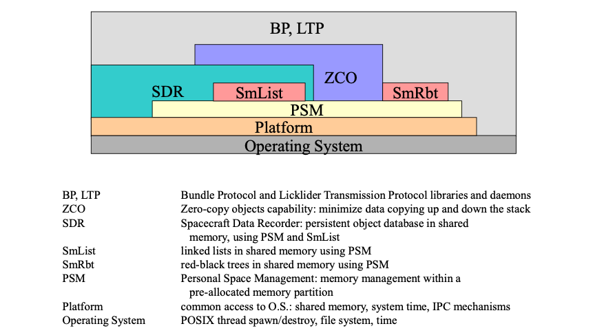
Figure 3 ION software functional dependencies
That is, BP and LTP invoke functions provided by the sdr, zco, psm, and platform elements of the ici package, in addition to functions provided by the operating system itself; the zco functions themselves also invoke sdr, psm, and platform functions; and so on.
Second, here is a summary view of the main line of data flow in ION's DTN protocol implementations:
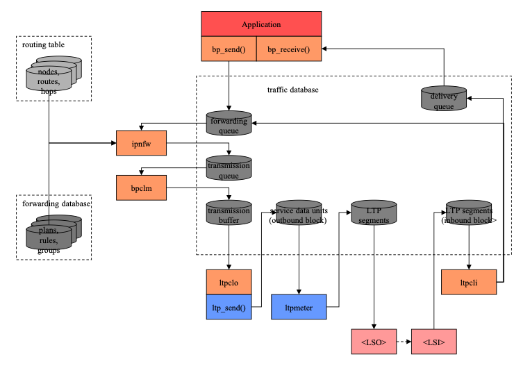
Figure 4 Main line of ION data flow
Note that data objects residing in shared memory, many of them in a nominally non-volatile SDR data store, constitute the central organizing principle of the design. Here as in other diagrams showing data flow in this document:
- Ordered collections of data objects are shown as cylinders.
- Darker greyscale data entities indicate data that are managed in the SDR data store, while lighter greyscale data entities indicate data that are managed in volatile DRAM to improve performance.
- Rectangles indicate processing elements (tasks, processes, threads), sometimes with library references specifically identified.
A few notes on this main line data flow:
- For simplicity, the data flow depicted here is a "loopback" flow in which a single BP "node" is shown sending data to itself (a useful configuration for test purposes). To depict typical operations over a network we would need two instances of this node diagram, such that the \<LSO> task of one node is shown sending data to the \<LSI> task of the other and vice versa.
- A BP application or application service (such as Remote AMS) that has access to the local BP node -- for our purposes, the "sender" -- invokes the bp_send function to send a unit of application data to a remote counterpart. The destination of the application data unit is expressed as a BP endpoint ID (EID). The application data unit is encapsulated in a bundle and is queued for forwarding.
- The forwarder task identified by the "scheme" portion of the bundle's destination EID removes the bundle from the forwarding queue and computes a route to the destination EID. The first node on the route is termed the "proximate node" for the computed route. The forwarder appends the bundle to the transmission queue for the convergence-layer manager (CLM) daemon that is responsible for transmission to the proximate node.
- The CLM daemon removes the bundle from the transmission queue and imposes rate control, fragments the bundle as necessary, and appends the bundle to the transmission buffer for some underlying "convergence layer" (CL) protocol interface to the proximate node, termed an outduct. In the event that multiple outducts are available for transmission to that node (e.g., multiple radio frequency bands), the CLM invokes mission-supplied code to select the appropriate duct. Each outduct is serviced by some CL-specific output task that communicates with the proximate node -- in this case, the LTP output task ltpclo. (Other CL protocols supported by ION include TCP and UDP.)
- The output task for LTP transmission to the selected proximate node removes the bundle from the transmission buffer and invokes the ltp_send function to append it to a block that is being assembled for transmission to the proximate node. (Because LTP acknowledgement traffic is issued on a per-block basis, we can limit the amount of acknowledgement traffic on the network by aggregating multiple bundles into a single block rather than transmitting each bundle in its own block.)
- The ltpmeter task for the selected proximate node divides the aggregated block into multiple segments and enqueues them for transmission by underlying link-layer transmission software, such as an implementation of the CCSDS AOS protocol.
- Underlying link-layer software at the sending node transmits the segments to its counterpart at the proximate node (the receiver), where they are used to reassemble the transmission block.
- The receiving node's input task for LTP reception extracts the bundles from the reassembled block and dispatches them: each bundle whose final destination is some other node is queued for forwarding, just like bundles created by local applications, while each bundle whose final destination is the local node is queued for delivery to whatever application "opens" the BP endpoint identified by the bundle's final destination endpoint ID. (Note that a multicast bundle may be both queued for forwarding, possibly to multiple neighboring nodes, and also queued for delivery.)
- The destination application or application service at the receiving node opens the appropriate BP endpoint and invokes the bp_receive function to remove the bundle from the associated delivery queue and extract the original application data unit, which it can then process.
Finally, note that the data flow shown here represents the sustained operational configuration of a node that has been successfully instantiated on a suitable computer. The sequence of operations performed to reach this configuration is not shown. That startup sequence will necessarily vary depending on the nature of the computing platform and the supporting link services. Broadly, the first step normally is to run the ionadmin utility program to initialize the data management infrastructure required by all elements of ION. Following this initialization, the next steps normally are (a) any necessary initialization of link service protocols, (b) any necessary initialization of convergence-layer protocols (e.g., LTP -- the ltpadmin utility program), and finally (c) initialization of the Bundle Protocol by means of the bpadmin utility program. BP applications should not try to commence operation until BP has been initialized.
Resource Management in ION
Successful Delay-Tolerant Networking relies on retention of bundle protocol agent state information -- including protocol traffic that is awaiting a transmission opportunity -- for potentially lengthy intervals. The nature of that state information will fluctuate rapidly as the protocol agent passes through different phases of operation, so efficient management of the storage resources allocated to state information is a key consideration in the design of ION.
Two general classes of storage resources are managed by ION: volatile "working memory" and non-volatile "heap".
- Working Memory
ION's "working memory" is a fixed-size pool of shared memory (dynamic RAM) that is allocated from system RAM at the time the bundle protocol agent commences operation. Working memory is used by ION tasks to store temporary data of all kinds: linked lists, red-black trees, transient buffers, volatile databases, etc. All intermediate data products and temporary data structures that ought not to be retained in the event of a system power cycle are written to working memory.
Data structures residing in working memory may be shared among ION tasks or may be created and managed privately by individual ION tasks. The dynamic allocation of working memory to ION tasks is accomplished by the Personal Space Management (PSM) service, described later. All of the working memory for any single ION bundle protocol agent is managed as a single PSM "partition". The size of the partition is specified in the wmSize parameter of the ionconfig file supplied at the time ION is initialized.
- Heap
ION's "heap" is a fixed-size pool of notionally non-volatile storage that is likewise allocated at the time the bundle protocol agent commences operation. This notionally non-volatile space may occupy a fixed-size pool of shared memory (dynamic RAM, which might or might not be battery-backed), or it may occupy only a single fixed-size file in the file system, or it may occupy both. In the latter case, all heap data are written both to memory and to the file but are read only from memory; this configuration offers the reliable non-volatility of file storage coupled with the high performance of retrieval from dynamic RAM.
We characterize ION's heap storage as "notionally" non-volatile because the heap may be configured to reside only in memory (or, for that matter, in a file that resides in the file system of a RAM disk). When the heap resides only in memory, its contents are truly non-volatile only if that memory is battery-backed. Otherwise heap storage is in reality as volatile as working memory: heap contents will be lost upon a system power cycle (which may in fact be the preferred behavior for any given deployment of ION). However, the heap should not be thought of as \"memory\" even when it in fact resides only in DRAM, just as a disk device should not be thought of as \"memory\" even when it is in fact a RAM disk.
 {width="4.738575021872266in"
height="3.338542213473316in"}
{width="4.738575021872266in"
height="3.338542213473316in"}
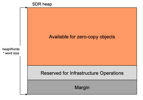
Figure 5 ION heap space use
The ION heap is used for storage of data that (in at least some deployments) would have to be retained in the event of a system power cycle to ensure the correct continued operation of the node. For example, all queues of bundles awaiting route computation, transmission, or delivery reside in the node's heap. So do the non-volatile databases for all of the protocols implemented within ION, together with all of the node's persistent configuration parameters.
The dynamic allocation of heap space to ION tasks is accomplished by the Simple Data Recorder (SDR) service, described later. The entire heap for any single ION bundle protocol agent is managed as a single SDR "data store".
Space within the ION heap is apportioned as shown in Figure 5. The total number of bytes of storage space in the heap is computed as the product of the size of a "word" on the deployment platform (normally the size of a pointer) multiplied by the value of the heapWords parameter of the ionconfig file supplied at the time ION is initialized. Of this total, 20% is normally reserved as margin and another 40% is normally reserved for various infrastructure operations. (Both of these percentages are macros that may be overridden at compile time.) The remainder is available for storage of protocol state data in the form of "zero-copy objects", described later. At any given moment, the data encapsulated in a zero-copy object may "belong" to any one of the protocols in the ION stack (AMS, CFDP, BP, LTP), depending on processing state; the available heap space is a single common resource to which all of the protocols share concurrent access.
Because the heap is used to store queues of bundles awaiting processing, blocks of LTP data awaiting transmission or reassembly, etc., the heap for any single ION node must be large enough to contain the maximum volume of such data that the node will be required to retain during operations. Demand for heap space is substantially mitigated if most of the application data units passed to ION for transmission are file-resident, as the file contents themselves need not be copied into the heap. In general, however, computing the optimum ION heap size for a given deployment remains a research topic.
Package Overviews
Interplanetary Communication Infrastructure (ICI)
The ICI package in ION provides a number of core services that, from ION's point of view, implement what amounts to an extended POSIX-based operating system. ICI services include the following:
1. Platform
The platform system contains operating-system-sensitive code that enables ICI to present a single, consistent programming interface to those common operating system services that multiple ION modules utilize. For example, the platform system implements a standard semaphore abstraction that may invisibly be mapped to underlying POSIX semaphores, SVR4 IPC semaphores, Windows Events, or VxWorks semaphores, depending on which operating system the package is compiled for. The platform system also implements a standard shared-memory abstraction, enabling software running on operating systems both with and without memory protection to participate readily in ION's shared-memory-based computing environment.
2. Personal Space Management (PSM)
Although sound flight software design may prohibit the uncontrolled dynamic management of system memory, private management of assigned, fixed blocks of system memory is standard practice. Often that private management amounts to merely controlling the reuse of fixed-size rows in static tables, but such techniques can be awkward and may not make the most efficient use of available memory. The ICI package provides an alternative, called PSM, which performs high-speed dynamic allocation and recovery of variable-size memory objects within an assigned memory block of fixed size. A given PSM-managed memory block may be either private or shared memory.
3. Memmgr
The static allocation of privately-managed blocks of system memory for different purposes implies the need for multiple memory management regimes, and in some cases a program that interacts with multiple software elements may need to participate in the private shared-memory management regimes of each. ICI's memmgr system enables multiple memory managers -- for multiple privately-managed blocks of system memory -- to coexist within ION and be concurrently available to ION software elements.
4. Lyst
The lyst system is a comprehensive, powerful, and efficient system for managing doubly-linked lists in private memory. It is the model for a number of other list management systems supported by ICI; as noted earlier, linked lists are heavily used in ION inter-task communication.
5. Llcv
The llcv (Linked-List Condition Variables) system is an inter-thread communication abstraction that integrates POSIX thread condition variables (vice semaphores) with doubly-linked lists in private memory.
6. Smlist
Smlist is another doubly-linked list management service. It differs from lyst in that the lists it manages reside in shared (rather than private) DRAM, so operations on them must be semaphore-protected to prevent race conditions.
7. SmRbt
The SmRbt service provides mechanisms for populating and navigating "red/black trees" (RBTs) residing in shared DRAM. RBTs offer an alternative to linked lists: like linked lists they can be navigated as queues, but locating a single element of an RBT by its "key" value can be much quicker than the equivalent search through an ordered linked list.
8. Simple Data Recorder (SDR)
SDR is a system for managing non-volatile storage, built on exactly the same model as PSM. Put another way, SDR is a small and simple "persistent object" system or "object database" management system. It enables straightforward management of linked lists (and other data structures of arbitrary complexity) in non-volatile storage, notionally within a single file whose size is pre-defined and fixed.
SDR includes a transaction mechanism that protects database integrity by ensuring that the failure of any database operation will cause all other operations undertaken within the same transaction to be backed out. The intent of the system is to assure retention of coherent protocol engine state even in the event of an unplanned flight computer reboot in the midst of communication activity.
9. Sptrace
The sptrace system is an embedded diagnostic facility that monitors the performance of the PSM and SDR space management systems. It can be used, for example, to detect memory "leaks" and other memory management errors.
10. Zco
ION's zco (zero-copy objects) system leverages the SDR system's storage flexibility to enable user application data to be encapsulated in any number of layers of protocol without copying the successively augmented protocol data unit from one layer to the next. It also implements a reference counting system that enables protocol data to be processed safely by multiple software elements concurrently -- e.g., a bundle may be both delivered to a local endpoint and, at the same time, queued for forwarding to another node -- without requiring that distinct copies of the data be provided to each element.
11. Rfx
The ION rfx (R/F Contacts) system manages lists of scheduled communication opportunities in support of a number of LTP and BP functions.
12. Ionsec
The IONSEC (ION security) system manages information that supports the implementation of security mechanisms in the other packages: security policy rules and computation keys.
Licklider Transmission Protocol (LTP)
The ION implementation of LTP conforms fully to RFC 5326, but it also provides two additional features that enhance functionality without affecting interoperability with other implementations:
- The service data units -- nominally bundles -- passed to LTP for transmission may be aggregated into larger blocks before segmentation. By controlling block size we can control the volume of acknowledgement traffic generated as blocks are received, for improved accommodation of highly asynchronous data rates.
- The maximum number of transmission sessions that may be concurrently managed by LTP (a protocol control parameter) constitutes a transmission "window" -- the basis for a delay-tolerant, non-conversational flow control service over interplanetary links.
In the ION stack, LTP serves effectively the same role that is performed by an LLC protocol (such as IEEE 802.2) in the Internet architecture, providing flow control and retransmission-based reliability between topologically adjacent bundle protocol agents.
All LTP session state is safely retained in the ION heap for rapid recovery from a spacecraft or software fault.
Bundle Protocol (BP)
The ION implementation of BP conforms fully to RFC 5050, including support for the following standard capabilities:
- Prioritization of data flows
- Proactive bundle fragmentation
- Bundle reassembly from fragments
- Flexible status reporting
- Custody transfer, including re-forwarding of custodial bundles upon timeout interval expiration or failure of nominally reliable convergence-layer transmission
The system also provides three additional features that enhance functionality without affecting interoperability with other implementations:
- Rate control provides support for congestion forecasting and avoidance.
- Bundle headers are encoded into compressed form (CBHE, as noted earlier) before issuance, to reduce protocol overhead and improve link utilization.
- Bundles may be "multicast" to all nodes that have registered within a given multicast group endpoint.
In addition, ION BP includes a system for computing dynamic routes through time-varying network topology assembled from scheduled, bounded communication opportunities. This system, called "Contact Graph Routing," is described later in this Guide.
In short, BP serves effectively the same role that is performed by IP in the Internet architecture, providing route computation, forwarding, congestion avoidance, and control over quality of service.
All bundle transmission state is safely retained in the ION heap for rapid recovery from a spacecraft or software fault.
Asynchronous Message Service (AMS)
The ION implementation of the CCSDS AMS standard conforms fully to CCSDS 735.0-B-1. AMS is a data system communications architecture under which the modules of mission systems may be designed as if they were to operate in isolation, each one producing and consuming mission information without explicit awareness of which other modules are currently operating. Communication relationships among such modules are self-configuring; this tends to minimize complexity in the development and operations of modular data systems.
A system built on this model is a "society" of generally autonomous inter-operating modules that may fluctuate freely over time in response to changing mission objectives, modules' functional upgrades, and recovery from individual module failure. The purpose of AMS, then, is to reduce mission cost and risk by providing standard, reusable infrastructure for the exchange of information among data system modules in a manner that is simple to use, highly automated, flexible, robust, scalable, and efficient.
A detailed discussion of AMS is beyond the scope of this Design Guide. For more information, please see the AMS Programmer's Guide.
Datagram Retransmission (DGR)
The DGR package in ION is an alternative implementation of LTP that is designed to operate responsibly -- i.e., with built-in congestion control -- in the Internet or other IP-based networks. It is provided as a candidate "primary transfer service" in support of AMS operations in an Internet-like (non-delay-tolerant) environment. The DGR design combines LTP's concept of concurrent transmission transactions with congestion control and timeout interval computation algorithms adapted from TCP.
CCSDS File Delivery Protocol (CFDP)
The ION implementation of CFDP conforms fully to Service Class 1 (Unreliable Transfer) of CCSDS 727.0-B-4, including support for the following standard capabilities:
- Segmentation of files on user-specified record boundaries.
- Transmission of file segments in protocol data units that are conveyed by an underlying Unitdata Transfer service, in this case the DTN protocol stack. File data segments may optionally be protected by CRCs. When the DTN protocol stack is configured for reliable data delivery (i.e., with BP custody transfer running over a reliable convergence-layer protocol such as LTP), file delivery is reliable; CFDP need not perform retransmission of lost data itself.
- Reassembly of files from received segments, possibly arriving over a variety of routes through the delay-tolerant network. The integrity of the delivered files is protected by checksums.
- User-specified fault handling procedures.
- Operations (e.g., directory creation, file renaming) on remote file systems.
All CFDP transaction state is safely retained in the ION heap for rapid recovery from a spacecraft or software fault.
Bundle Streaming Service (BSS)
The BSS service provided in ION enables a stream of video, audio, or other continuously generated application data units, transmitted over a delay-tolerant network, to be presented to a destination application in two useful modes concurrently:
- In the order in which the data units were generated, with the least possible end-to-end delivery latency, but possibly with some gaps due to transient data loss or corruption.
- In the order in which the data units were generated, without gaps (i.e., including lost or corrupt data units which were omitted from the real-time presentation but were subsequently retransmitted), but in a non-real-time "playback" mode.
Trusted Collective (TC)
The TC service provided in ION enables critical but non-confidential information (such as public keys, for asymmetric cryptography) to be provided in a delay-tolerant, trustworthy manner. An instance of TC comprises:
- A distributed Authority, the members of which must reach consensus on database content and must collaborate on the proactive distribution of that content.
-
Any number of Clients, which:
-
Announce new content to the Authority via authenticated bundle multicast, and/or
- Receive trustworthy bulletins multicast by the members of the Authority.
Acronyms
| Acronyms | Description |
|---|---|
| BP | Bundle Protocol |
| BSP | Bundle Security Protocol |
| BSS | Bundle Streaming Service |
| CCSDS | Consultative Committee for Space Data Systems |
| CFDP | CCSDS File Delivery Protocol |
| CGR | Contact Graph Routing |
| CL | convergence layer |
| CLI | convergence layer input |
| CLO | convergence layer output |
| DTKA | Delay-Tolerant Key Administration |
| DTN | Delay-Tolerant Networking |
| ICI | Interplanetary Communication Infrastructure |
| ION | Interplanetary Overlay Network |
| LSI | link service input |
| LSO | link service output |
| LTP | Licklider Transmission Protocol |
| OWLT | one-way light time |
| RFC | request for comments |
| RFX | Radio (R/F) Contacts |
| RTT | round-trip time |
| TC | Trusted Collective |
| TTL | time to live |
Network Operation Concepts
A small number of network operation design elements -- fragmentation and reassembly, bandwidth management, and delivery assurance (retransmission) -- can potentially be addressed at multiple layers of the protocol stack, possibly in different ways for different reasons. In stack design it's important to allocate this functionality carefully so that the effects at lower layers complement, rather than subvert, the effects imposed at higher layers of the stack. This allocation of functionality is discussed below, together with a discussion of several related key concepts in the ION design.
Fragmentation and Reassembly
To minimize transmission overhead and accommodate asymmetric links (i.e., limited "uplink" data rate from a ground data system to a spacecraft) in an interplanetary network, we ideally want to send "downlink" data in the largest possible aggregations -- coarse-grained transmission.
But to minimize head-of-line blocking (i.e., delay in transmission of a newly presented high-priority item) and minimize data delivery latency by using parallel paths (i.e., to provide fine-grained partial data delivery, and to minimize the impact of unexpected link termination), we want to send "downlink" data in the smallest possible aggregations -- fine-grained transmission.
We reconcile these impulses by doing both, but at different layers of the ION protocol stack.
First, at the application service layer (AMS and CFDP) we present relatively small application data units (ADUs) -- on the order of 64 KB -- to BP for encapsulation in bundles. This establishes an upper bound on head-of-line blocking when bundles are de-queued for transmission, and it provides perforations in the data stream at which forwarding can readily be switched from one link (route) to another, enabling partial data delivery at relatively fine, application-appropriate granularity.
(Alternatively, large application data units may be presented to BP and the resulting large bundles may be proactively fragmented at the time they are presented to the convergence-layer manager. This capability is meant to accommodate environments in which the convergence-layer manager has better information than the application as to the optimal bundle size, such as when the residual capacity of a contact is known to be less than the size of the bundle.)
Then, at the BP/LTP convergence layer adapter lower in the stack, we aggregate these small bundles into blocks for presentation to LTP:
Any continuous sequence of bundles that are to be shipped to the same LTP engine and all require assured delivery may be aggregated into a single block, to reduce overhead and minimize report traffic.
However, this aggregation is constrained by an aggregation size limit rule: aggregation must stop and the block must be transmitted as soon as the sum of the sizes of all bundles aggregated into the block exceeds the block aggregation threshhold value declared for the applicable span (the relationship between the local node's LTP engine and the receiving LTP engine) during LTP protocol configuration via ltpadmin.
Given a preferred block acknowledgment period -- e.g., a preferred acknowledgement traffic rate of one report per second -- the nominal block aggregation threshold is notionally computed as the amount of data that can be sent over the link to the receiving LTP engine in a single block acknowledgment period at the planned outbound data rate to that engine.
Taken together, application-level fragmentation (or BP proactive fragmentation) and LTP aggregation place an upper limit on the amount of data that would need to be re-transmitted over a given link at next contact in the event of an unexpected link termination that caused delivery of an entire block to fail. For example, if the data rate is 1 Mbps and the nominal block size is 128 KB (equivalent to 1 second of transmission time), we would prefer to avoid the risk of having wasted five minutes of downlink in sending a 37.5 MB file that fails on transmission of the last kilobyte, forcing retransmission of the entire 37.5 MB. We therefore divide the file into, say, 1200 bundles of 32 KB each which are aggregated into blocks of 128 KB each: only a single block failed, so only that block (containing just 4 bundles) needs to be retransmitted. The cost of this retransmission is only 1 second of link time rather than 5 minutes. By controlling the cost of convergence-layer protocol failure in this way, we avoid the overhead and complexity of "reactive fragmentation" in the BP implementation.
Finally, within LTP itself we fragment the block as necessary to accommodate the Maximum Transfer Unit (MTU) size of the underlying link service, typically the transfer frame size of the applicable CCSDS link protocol.
Bandwidth Management
The allocation of bandwidth (transmission opportunity) to application data is requested by the application task that's passing data to DTN, but it is necessarily accomplished only at the lowest layer of the stack at which bandwidth allocation decisions can be made -- and then always in the context of node policy decisions that have global effect.
The transmission queue interface to a given neighbor in the network is actually three queues of outbound bundles rather than one: one queue for each of the defined levels of priority ("class of service") supported by BP. When an application presents an ADU to BP for encapsulation in a bundle, it indicates its own assessment of the ADU's priority. Upon selection of a proximate forwarding destination node for that bundle, the bundle is appended to whichever of the queues corresponds to the ADU's priority.
Normally the convergence-layer manager (CLM) task servicing a given proximate node extracts bundles in strict priority order from the heads of the three queues. That is, the bundle at the head of the highest-priority non-empty queue is always extracted.
However, if the ION_BANDWIDTH_RESERVED compiler option is selected at the time ION is built, the convergence-layer manager task servicing a given proximate node extracts bundles in interleaved fashion from the heads of the node's three queues:
- Whenever the priority-2 ("express") queue is non-empty, the bundle at the head of that queue is the next one extracted.
- At all other times, bundles from both the priority-1 queue and the priority-0 queue are extracted, but over a given period of time twice as many bytes of priority-1 bundles will be extracted as bytes of priority-0 bundles.
Following insertion of the extracted bundles into transmission buffers, CLO tasks other than ltpclo simply segment the buffered bundles as necessary and transmit them using the underlying convergence-layer protocols. In the case of ltpclo, the output task aggregates the buffered bundles into blocks as described earlier and a second daemon task named ltpmeter waits for aggregated blocks to be completed; ltpmeter, rather than the CLO task itself, segments each completed block as necessary and passes the segments to the link service protocol that underlies LTP. Either way, the transmission ordering requested by application tasks is preserved.
Contact Plans
In the Internet, protocol operations can be largely driven by currently effective information that is discovered opportunistically and immediately, at the time it is needed, because the latency in communicating this information over the network is negligible: distances between communicating entities are small and connectivity is continuous. In a DTN-based network, however, ad-hoc information discovery would in many cases take so much time that it could not be completed before the information lost currency and effectiveness. Instead, protocol operations must be largely driven by information that is pre-placed at the network nodes and tagged with the dates and times at which it becomes effective. This information takes the form of contact plans that are managed by the R/F Contacts (rfx) services of ION's ici package.
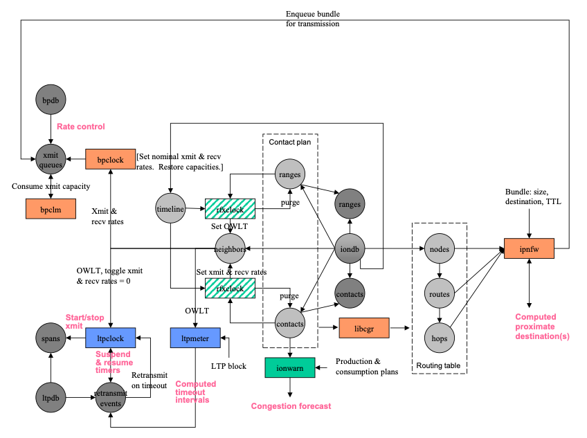
Figure 6 RFX services in ION
The structure of ION's RFX (contact plan) database, the rfx system elements that populate and use that data, and affected portions of the BP and LTP protocol state databases are shown in Figure 6. (For additional details of BP and LTP database management, see the BP/LTP discussion later in this document.)
To clarify the notation of this diagram, which is also used in other database structure diagrams in this document:
- Data objects of defined structure are shown as circles. Dark greyscale indicates notionally non-volatile data retained in "heap" storage, while lighter greyscale indicates volatile data retained in dynamic random access memory.
- Solid arrows connecting circles indicate one-to-many cardinality.
- A dashed arrow between circles indicates a potentially many-to-one reference mapping.
- Arrows from processing elements (rectangles) to data entities indicate data production, while arrows from data entities to processing elements indicate data retrieval.
A contact is here defined as an interval during which it is expected that data will be transmitted by DTN node A (the contact's transmitting node) and most or all of the transmitted data will be received by node B (the contact's receiving node). Implicitly, the transmitting mode will utilize some "convergence-layer" protocol underneath the Bundle Protocol to effect this direct transmission of data to the receiving node. Each contact is characterized by its start time, its end time, the identities of the transmitting and receiving nodes, and the rate at which data are expected to be transmitted by the transmitting node throughout the indicated time period.
(Note that a contact is specifically not an episode of activity on a link. Episodes of activity on different links -- e.g., different radio transponders operating on the same spacecraft -- may well overlap, but contacts by definition cannot; they are bounded time intervals and as such are innately "tiled". For example, suppose transmission on link X from node A to node B, at data rate RX, begins at time T1 and ends at time T2; also, transmission on link Y from node A to node B, at data rate RY begins at time T3 and ends at time T4. If T1 = T3 and T2 = T4, then there is a single contact from time T1 to time T2 at data rate RX + RY. If T1 \< T3 and T2 = T4, then there are two contiguous contacts: one from T1 to T3 at data rate RX, then one from T3 to T2 at data rate RX + RY. If T1 \< T3 and T3\<T2 \< T4, then there are three contiguous contacts: one from T1 to T3 at data rate RX, then one from T3 to T2 at data rate RX + RY, then one from T2 to T4 at data rate RY. And so on.)
A range interval is a period of time during which the displacement between two nodes A and B is expected to vary by less than 1 light second from a stated anticipated distance. (We expect this information to be readily computable from the known orbital elements of all nodes.) Each range interval is characterized by its start time, its end time, the identities of the two nodes to which it pertains, and the anticipated approximate distance between those nodes throughout the indicated time period, to the nearest light second.
The topology timeline at each node in the network is a time-ordered list of scheduled or anticipated changes in the topology of the network. Entries in this list are of two types:
• Contact entries characterize scheduled contacts.
• Range entries characterize anticipated range intervals.
Each node to which, according to the RFX database, the local node transmits data directly via some convergence-layer protocol at some time is termed a neighbor of the local node. Each neighbor is associated with one or more outduct for the applicable BP convergence-layer (CL) protocol adapter(s), so bundles that are to be transmitted directly to this neighbor can simply be queued for transmission by outduct (as discussed in the Bandwidth Management notes above).
At startup, and at any time while the system is running, ionadmin inserts and removes Contact and Range entries in the topology timeline of the RFX database. Inserting or removing a Contact or Range entry will cause routing tables to be recomputed for the destination nodes of all subsequently forwarded bundles, as described in the discussion of Contact Graph Routing below.
Once per second, the rfxclock task (which appears in multiple locations on the diagram to simplify the geometry) applies all topology timeline events (Contact and Range start, stop, purge) with effective time in the past. Applying a Contact event that cites a neighboring node revises the transmission or reception data rate between the local node and that Neighbor. Applying a Range event that cites a neighboring node revises the OWLT between the local node and that neighbor. Setting data rate or OWLT for a node with which the local node will at some time be in direct communication may entail creation of a Neighbor object.
Route Computation
ION's computation of a route for a given bundle with a given destination endpoint is accomplished by one of several methods, depending on the destination. In every case, the result of successful routing is the insertion of the bundle into an outbound transmission queue (selected according to the bundle's priority) for one or more neighboring nodes.
But before discussing these methods it will be helpful to establish some terminology:
Egress plans
ION can only forward bundles to a neighboring node by queuing them on some explicitly specified transmission queue. Specifications that associate neighboring nodes with outducts are termed egress plans. They are retained in ION's unicast forwarding database.
Static routes
ION can be configured to forward to some specified node all bundles that are destined for a given node to which no dynamic route can be discovered from an examination of the contact graph, as described later. Static routing is implemented by means of the "exit" mechanism described below.
Unicast
When the destination of a bundle is a single node that is registered within a known "singleton endpoint" (that is, an endpoint that is known to have exactly one member), then transmission of that bundle is termed unicast. For this purpose, the destination endpoint ID must be a URI formed in either the "dtn" scheme (e.g., dtn://bobsmac/mail) or the "ipn" scheme (e.g., ipn:913.11).
Exits
When unicast routes must be computed to nodes for which no contact plan information is known (e.g., the size of the network makes it impractical to distribute all Contact and Range information for all nodes to every node, or the destination nodes don't participate in Contact Graph Routing at all), the job of computing routes to all nodes may be partitioned among multiple exit nodes. Each exit is responsible for managing routing information (for example, a comprehensive contact graph) for some subset of the total network population -- a group comprising all nodes whose node numbers fall within the range of node numbers assigned to the exit. A bundle destined for a node for which no dynamic route can be computed from the local node's contact graph may be routed to the exit node for the group within whose range the destination's node number falls. Exits are defined in ION's unicast forwarding database. (Note that the exit implements static routes in ION in addition to improving scalability.)
Multicast
When the destination of a bundle is all nodes that are registered within a known "multicast endpoint" (that is, an endpoint that is not known to have exactly one member), then transmission of that bundle is termed multicast. For this purpose (in ION), the destination endpoint ID must be a URI formed in the "imc" scheme (e.g., imc:913.11).
Multicast Groups
A multicast group is the set of all nodes in the network that are members of a given multicast endpoint. Forwarding a bundle to all members of its destination multicast endpoint is the responsibility of all of the multicast-aware nodes of the network. These nodes are additionally configured to be nodes of a single multicast spanning tree overlaid onto the dtnet. A single multicast tree serves to forward bundles to all multicast groups: each node of the tree manages petitions indicating which of its "relatives" (parent and children) are currently interested in bundles destined for each multicast endpoint, either natively (due to membership in the indicated group) or on behalf of more distant relatives.
Unicast
We begin unicast route computation by attempting to compute a dynamic route to the bundle's final destination node. The details of this algorithm are described in the section on Contact Graph Routing, below.
If no dynamic route can be computed, but the final destination node is a "neighboring" node that is directly reachable, then we assume that taking this direct route is the best strategy unless transmission to that neighbor is flagged as "blocked" for network operations purposes.
Otherwise we must look for a static route. If the bundle's destination node number is in one of the ranges of node numbers assigned to exit nodes, then we forward the bundle to the exit node for the smallest such range. (If the exit node is a neighbor and transmission to that neighbor is not blocked, we simply queue the bundle for transmission to that neighbor; otherwise we similarly look up the static route for the exit node until eventually we resolve to some egress plan.)
If we can determine neither a dynamic route nor a static route for this bundle, but the reason for this failure was transmission blockage that might be resolved in the future, then the bundle is placed in a "limbo" list for future re-forwarding when transmission to some node is "unblocked."
Otherwise, the bundle cannot be forwarded. If custody transfer is requested for the bundle, we send a custody refusal to the bundle's current custodian; in any case, we discard the bundle.
Multicast
Multicast route computation is much simpler.
- When an endpoint for the "imc" scheme is added on an ION node -- that is, when the node joins that multicast endpoint -- BP administrative records noting the node's new interest in the application topic corresponding to the endpoint's group number are multicast to other network nodes as needed, using a "built-in" multicast group of which all nodes of the network are implicitly members. On receipt of such a record, each node notes the sending relative's interest and forwards the record to other nodes as necessary, and so on. (Deletion of endpoints results in similar propagation of cancelling administrative records.)
-
A bundle whose destination endpoint cites a multicast group, whether locally sourced or received from another node:
-
Is delivered immediately, if the local node is a member of the indicated endpoint.
- Is queued for direct transmission to all other nodes in the local "region" of network topology that are members of the multicast group. Passageway nodes forward the bundle as necessary into other regions that are topologically adjacent to the local region.
Delivery Assurance
End-to-end delivery of data can fail in many ways, at different layers of the stack. When delivery fails, we can either accept the communication failure or retransmit the data structure that was transmitted at the stack layer at which the failure was detected. ION is designed to enable retransmission at multiple layers of the stack, depending on the preference of the end user application.
At the lowest stack layer that is visible to ION, the convergence-layer protocol, failure to deliver one or more segments due to segment loss or corruption will trigger segment retransmission if a "reliable" convergence-layer protocol is in use: LTP "red-part" transmission or TCP (including Bundle Relay Service, which is based on TCP)1.
Segment loss may be detected and signaled via NAK by the receiving entity, or it may only be detected at the sending entity by expiration of a timer prior to reception of an ACK. Timer interval computation is well understood in a TCP environment, but it can be a difficult problem in an environment of scheduled contacts as served by LTP. The round-trip time for an acknowledgment dialogue may be simply twice the one-way light time (OWLT) between sender and receiver at one moment, but it may be hours or days longer at the next moment due to cessation of scheduled contact until a future contact opportunity. To account for this timer interval variability in retransmission, the ltpclock task infers the initiation and cessation of LTP transmission, to and from the local node, from changes in the current xmit and recv data rates in the corresponding Neighbor objects. This controls the dequeuing of LTP segments for transmission by underlying link service adapter(s) and it also controls suspension and resumption of timers, removing the effects of contact interruption from the retransmission regime. For a further discussion of this mechanism, see the section below on LTP Timeout Intervals.
Note that the current OWLT in Neighbor objects is also used in the computation of the nominal expiration times of timers and that ltpclock is additionally the agent for LTP segment retransmission based on timer expiration.
It is, of course, possible for the nominally reliable convergence-layer protocol to fail altogether: a TCP connection might be abruptly terminated, or an LTP transmission might be canceled due to excessive retransmission activity (again possibly due to an unexpected loss of connectivity). In this event, BP itself detects the CL protocol failure and re-forwards all bundles whose acquisition by the receiving entity is presumed to have been aborted by the failure. This re-forwarding is initiated in different ways for different CL protocols, as implemented in the CL input and output adapter tasks. If immediate re-forwarding is impossible because transmission to all potentially viable neighbors is blocked, the affected bundles are placed in the limbo list for future re-forwarding when transmission to some node is unblocked.
In addition to the implicit forwarding failure detected when a CL protocol fails, the forwarding of a bundle may be explicitly refused by the receiving entity, provided the bundle is flagged for custody transfer service. A receiving node's refusal to take custody of a bundle may have any of a variety of causes: typically the receiving node either (a) has insufficient resources to store and forward the bundle, (b) has no route to the destination, or (c) will have no contact with the next hop on the route before the bundle's TTL has expired. In any case, a "custody refusal signal" (packaged in a bundle) is sent back to the sending node, which must re-forward the bundle in hopes of finding a more suitable route.
Alternatively, failure to receive a custody acceptance signal within some convergence-layer-specified or application-specified time interval may also be taken as an implicit indication of forwarding failure. Here again, when BP detects such a failure it attempts to re-forward the affected bundle, placing the bundle in the limbo list if re-forwarding is currently impossible.
In the worst case, the combined efforts of all the retransmission mechanisms in ION are not enough to ensure delivery of a given bundle, even when custody transfer is requested. In that event, the bundle's "time to live" will eventually expire while the bundle is still in custody at some node: the bpclock task will send a bundle status report to the bundle's report-to endpoint, noting the TTL expiration, and destroy the bundle. The report-to endpoint, upon receiving this report, may be able to initiate application-layer retransmission of the original application data unit in some way. This final retransmission mechanism is wholly application-specific, however.
Rate Control
In the Internet, the rate of transmission at a node can be dynamically negotiated in response to changes in level of activity on the link, to minimize congestion. On deep space links, signal propagation delays (distances) may be too great to enable effective dynamic negotiation of transmission rates. Fortunately, deep space links are operationally reserved for use by designated pairs of communicating entities over pre-planned periods of time at pre-planned rates. Provided there is no congestion inherent in the contact plan, congestion in the network can be avoided merely by adhering to the planned contact periods and data rates. Rate control in ION serves this purpose.
While the system is running, transmission and reception of bundles is constrained by the current capacity in the throttle of each convergence-layer manager. Completed bundle transmission activity reduces the current capacity of the applicable throttle by the capacity consumption computed for that bundle. This reduction may cause the throttle's current capacity to become negative. Once the current capacity of the applicable throttle goes negative, activity is blocked until non-negative capacity has been restored by bpclock.
Once per second, the bpclock task increases the current capacity of each throttle by one second's worth of traffic at the nominal data rate for transmission to that node, thus enabling some possibly blocked bundle transmission and reception to proceed.
bpclock revises all throttles' nominal data rates once per second in accord with the current data rates in the corresponding Neighbor objects, as adjusted by rfxclock per the contact plan.
Note that this means that, for any neighboring node for which there are planned contacts, ION's rate control system will enable data flow only while contacts are active.
Flow Control
A further constraint on rates of data transmission in an ION-based network is LTP flow control. LTP is designed to enable multiple block transmission sessions to be in various stages of completion concurrently, to maximize link utilization: there is no requirement to wait for one session to complete before starting the next one. However, if unchecked this design principle could in theory result in the allocation of all memory in the system to incomplete LTP transmission sessions. To prevent complete storage resource exhaustion, we set a firm upper limit on the total number of outbound blocks that can be concurrently in transit at any given time. These limits are established by ltpadmin at node initialization time.
The maximum number of transmission sessions that may be concurrently managed by LTP therefore constitutes a transmission "window" -- the basis for a delay-tolerant, non-conversational flow control service over interplanetary links. Once the maximum number of sessions are in flight, no new block transmission session can be initiated -- regardless of how much outduct transmission capacity is provided by rate control -- until some existing session completes or is canceled.
Note that this consideration emphasizes the importance of configuring the aggregation size limits and session count limits of spans during LTP initialization to be consistent with the maximum data rates scheduled for contacts over those spans.
Storage Management
Congestion in a dtnet is the imbalance between data enqueuing and dequeuing rates that results in exhaustion of queuing (storage) resources at a node, preventing continued operation of the protocols at that node.
In ION, the affected queuing resources are allocated from notionally non-volatile storage space in the SDR data store and/or file system. The design of ION is required to prevent resource exhaustion by simply refusing to enqueue additional data that would cause it.
However, a BP router's refusal to enqueue received data for forwarding could result in costly retransmission, data loss, and/or the "upstream" propagation of resource exhaustion to other nodes. Therefore the ION design additionally attempts to prevent potential resource exhaustion by forecasting levels of queuing resource occupancy and reporting on any congestion that is predicted. Network operators, upon reviewing these forecasts, may revise contact plans to avert the anticipated resource exhaustion.
The non-volatile storage used by ION serves several purposes: it contains queues of bundles awaiting forwarding, transmission, and delivery; it contains LTP transmission and reception sessions, including the blocks of data that are being transmitted and received; it contains queues of LTP segments awaiting radiation; it may contain CFDP transactions in various stages of completion; and it contains protocol operational state information, such as configuration parameters, static routes, the contact graph, etc.
Effective utilization of non-volatile storage is a complex problem. Static pre-allocation of storage resources is in general less efficient (and also more labor-intensive to configure) than storage resource pooling and automatic, adaptive allocation: trying to predict a reasonable maximum size for every data storage structure and then rigidly enforcing that limit typically results in underutilization of storage resources and underperformance of the system as a whole. However, static pre-allocation is mandatory for safety-critical resources, where certainty of resource availability is more important than efficient resource utilization.
The tension between the two approaches is analogous to the tension between circuit switching and packet switching in a network: circuit switching results in underutilization of link resources and underperformance of the network as a whole (some peaks of activity can never be accommodated, even while some resources lie idle much of the time), but dedicated circuits are still required for some kinds of safety-critical communication.
So the ION data management design combines these two approaches (see 1.5 above for additional discussion of this topic):
- A fixed percentage of the total SDR data store heap size (by default, 40%) is statically allocated to the storage of protocol operational state information, which is critical to the operation of ION.
- Another fixed percentage of the total SDR data store heap size (by default, 20%) is statically allocated to "margin", a reserve that helps to insulate node management from errors in resource allocation estimates.
- The remainder of the heap, plus all pre-allocated file system space, is allocated to protocol traffic2.
The maximum projected occupancy of the node is the result of computing a congestion forecast for the node, by adding to the current occupancy all anticipated net increases and decreases from now until some future time, termed the horizon for the forecast.
The forecast horizon is indefinite -- that is, "forever" -- unless explicitly declared by network management via the ionadmin utility program. The difference between the horizon and the current time is termed the interval of the forecast.
Net occupancy increases and decreases are of four types:
- Bundles that are originated locally by some application on the node, which are enqueued for forwarding to some other node.
- Bundles that are received from some other node, which are enqueued either for forwarding to some other node or for local delivery to an application.
- Bundles that are transmitted to some other node, which are dequeued from some forwarding queue.
- Bundles that are delivered locally to an application, which are dequeued from some delivery queue.
The type-1 anticipated net increase (total data origination) is computed by multiplying the node's projected rate of local data production, as declared via an ionadmin command, by the interval of the forecast. Similarly, the type-4 anticipated net decrease (total data delivery) is computed by multiplying the node's projected rate of local data consumption, as declared via an ionadmin command, by the interval of the forecast. Net changes of types 2 and 3 are computed by multiplying inbound and outbound data rates, respectively, by the durations of all periods of planned communication contact that begin and/or end within the interval of the forecast.
Congestion forecasting is performed by the ionwarn utility program. ionwarn may be run independently at any time; in addition, the ionadmin utility program automatically runs ionwarn immediately before exiting if it executed any change in the contact plan, the forecast horizon, or the node's projected rates of local data production or consumption. Moreover, the rfxclock daemon program also runs ionwarn automatically whenever any of the scheduled reconfiguration events it dispatches result in contact state changes that might alter the congestion forecast.
If the final result of the forecast computation -- the maximum projected occupancy of the node over the forecast interval -- is less than the total protocol traffic allocation, then no congestion is forecast. Otherwise, a congestion forecast status message is logged noting the time at which maximum projected occupancy is expected to equal the total protocol traffic allocation.
Congestion control in ION, then, has two components:
First, ION's congestion detection is anticipatory (via congestion forecasting) rather than reactive as in the Internet.
Anticipatory congestion detection is important because the second component -- congestion mitigation -- must also be anticipatory: it is the adjustment of communication contact plans by network management, via the propagation of revised schedules for future contacts.
(Congestion mitigation in an ION-based network is likely to remain mostly manual for many years to come, because communication contact planning involves much more than orbital dynamics: science operations plans, thermal and power constraints, etc. It will, however, rely on the automated rate control features of ION, discussed above, which ensure that actual network operations conform to established contact plans.)
Rate control in ION is augmented by admission control. ION tracks the sum of the sizes of all zero-copy objects currently residing in the heap and file system at any moment. Whenever any protocol implementation attempts to create or extend a ZCO in such a way that total heap or file occupancy would exceed an upper limit asserted for the node, that attempt is either blocked until ZCO space becomes available or else rejected altogether.
Optimizing an ION-based network
ION is designed to deliver critical data to its final destination with as much certainty as possible (and optionally as soon as possible), but otherwise to try to maximize link utilization. The delivery of critical data is expedited by contact graph routing and bundle prioritization as described elsewhere. Optimizing link utilization, however, is a more complex problem.
If the volume of data traffic offered to the network for transmission is less than the capacity of the network, then all offered data should be successfully delivered3. But in that case the users of the network are paying the opportunity cost of whatever portion of the network capacity was not used.
Offering a data traffic volume that is exactly equal to the capacity of the network is in practice infeasible. TCP in the Internet can usually achieve this balance because it exercises end-to-end flow control: essentially, the original source of data is blocked from offering a message until notified by the final destination that transmission of this message can be accommodated given the current negotiated data rate over the end-to-end path (as determined by TCP's congestion control mechanisms). In a delay-tolerant network no such end-to-end negotiated data rate may exist, much less be knowable, so such precise control of data flow is impossible.4
The only alternative: the volume of traffic offered by the data source must be greater than the capacity of the network and the network must automatically discard excess traffic, shedding lower-priority data in preference to high-priority messages on the same path.
ION discards excess traffic proactively when possible and reactively when necessary.
Proactive data triage occurs when ION determines that it
cannot compute a route that will deliver a given bundle to its final
destination prior to expiration of the bundle's Time To Live (TTL). That
is, a bundle may be discarded simply because its TTL is too short, but
more commonly it will be discarded because the planned contacts to
whichever neighboring node is first on the path to the destination are
already fully subscribed: the queue of bundles awaiting transmission to
that neighbor is already so long as to consume the entire capacity of
all announced opportunities to transmit to it. Proactive data triage
causes the bundle to be immediately destroyed as one for which there is
"No known route to destination from here."
The determination of the degree to which a contact is subscribed is based not only on the aggregate size of the queued bundles but also on the estimated aggregate size of the overhead imposed by all the convergence-layer (CL) protocol data units -- at all layers of the underlying stack -- that encapsulate those bundles: packet headers, frame headers, etc. This means that the accuracy of this overhead estimate will affect the aggressiveness of ION's proactive data triage:
- If CL overhead is overestimated, the size of the bundle transmission backlog for planned contacts will be overstated, unnecessarily preventing the enqueuing of additional bundles -- a potential under-utilization of available transmission capacity in the network.
- If CL overhead is underestimated, the size of the bundle transmission backlog for planned contacts will be understated, enabling the enqueuing of bundles whose transmission cannot in fact be accomplished by the network within the constraints of the current contact plan. This will eventually result in reactive data triage.
Essentially, all reactive data triage -- the destruction
of bundles due to TTL expiration prior to successful delivery to the
final destination -- occurs when the network conveys bundles at lower
net rates than were projected during route computation. These
performance shortfalls can have a variety of causes:
- As noted above, underestimating CL overhead causes CL overhead to consume a larger fraction of contact capacity than was anticipated, leaving less capacity for bundle transmission.
- Conversely, the total volume of traffic offered may have been accurately estimated but the amount of contact capacity may be less than was promised: a contact might be started late, stopped early, or omitted altogether, or the actual data rate on the link might be less than was advertised.
- Contacts may be more subtly shortened by the configuration of ION itself. If the clocks on nodes are known not to be closely synchronized then a "maximum clock error" of N seconds may be declared, causing reception episodes to be started locally N seconds earlier and stopped N seconds later than scheduled, to avoid missing some transmitted data because it arrived earlier or later than anticipated. But this mechanism also causes transmission episodes to be started N seconds later and stopped N seconds earlier than scheduled, to avoid transmitting to a neighbor before it is ready to receive data, and this contact truncation ensures transmission of fewer bundles than planned.
- Flow control within the convergence layer underlying the bundle protocol may constrain the effective rate of data flow over a link to a rate that's lower than the link's configured maximum data rate. In particular, mis-configuration of the LTP flow control window can leave transmission capacity unused while LTP engines are awaiting acknowledgments.
- Even if all nodes are correctly configured, a high rate of data loss or corruption due to unexpectedly high R/F interference or underestimated acknowledgment round-trip times may cause an unexpectedly high volume of retransmission traffic. This will displace original bundle transmission, reducing the effective "goodput" data rate on the link.
- Finally, custody transfer may propagate operational problems from one part of the network to other nodes. One result of reduced effective transmission rates is the accumulation of bundles for which nodes have taken custody: the custodial nodes can't destroy those bundles and reclaim the storage space they occupy until custody has been accepted by "downstream" nodes, so abbreviated contacts that prevent the flow of custody acceptances can increase local congestion. This reduces nodes' own ability to take custody of bundles transmitted by "upstream" custodians, increasing queue sizes on those nodes, and so on. In short, custody transfer may itself ultimately impose reactive data triage simply by propagating congestion.
Some level of data triage is essential to cost-effective network utilization, and proactive triage is preferable because its effects can be communicated immediately to users, improving user control over the use of the network. Optimizing an ION-based network therefore amounts to managing for a modicum of proactive data triage and as little reactive data triage as possible. It entails the following:
- Estimating convergence-layer protocol overhead as accurately as possible, erring (if necessary) on the side of optimism -- that is, underestimating a little.
As an example, suppose the local node uses LTP over CCSDS Telemetry to send bundles. The immediate convergence-layer protocol is LTP, but the total overhead per CL "frame" (in this case, per LTP segment) will include not only the size of the LTP header (nominally 5 bytes) but also the size of the encapsulating space packet header (nominally 6 bytes) and the overhead imposed by the outer encapsulating TM frame.
Suppose each LTP segment is to be wrapped in a single space packet, which is in turn wrapped in a single TM frame, and Reed-Solomon encoding is applied. An efficient TM frame size is 1115 bytes, with an additional 160 bytes of trailing Reed-Solomon encoding and another 4 bytes of leading pseudo-noise code. The frame would contain a 6-byte TM frame header, a 6-byte space packet header, a 5-byte LTP segment header, and 1098 bytes of some LTP transmission block.
So the number of "payload bytes per frame" in this case would be 1098 and the number of "overhead bytes per frame" would be 4 + 6 + 6 + 5 + 160 = 181. Nominal total transmission overhead on the link would be 181 / 1279 = about 14%. 2. Synchronizing nodes' clocks as accurately as possible, so that timing margins configured to accommodate clock error can be kept as close to zero as possible. 3. Setting the LTP session limit and block size limit as generously as possible (whenever LTP is at the convergence layer), to assure that LTP flow control does not constrain data flow to rates below those supported by BP rate control. 4. Setting ranges (one-way light times) and queuing delays as accurately as possible, to prevent unnecessary retransmission. Err on the side of pessimism -- that is, overestimate a little. 5. Communicating changes in configuration -- especially contact plans -- to all nodes as far in advance of the time they take effect as possible. 6. Providing all nodes with as much storage capacity as possible for queues of bundles awaiting transmission.
BP/LTP Detail -- How They Work
Although the operation of BP/LTP in ION is complex in some ways, virtually the entire system can be represented in a single diagram. The interactions among all of the concurrent tasks that make up the node -- plus a Remote AMS task or CFDP UT-layer task, acting as the application at the top of the stack -- are shown below. (The notation is as used earlier but with semaphores added. Semaphores are shown as small circles, with arrows pointing into them signifying that the semaphores are being given and arrows pointing out of them signifying that the semaphores are being taken.)
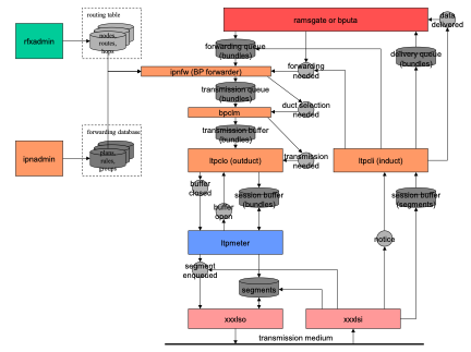
Figure 7 ION node functional overview
Further details of the BP/LTP data structures and flow of control and data appear on the following pages. (For specific details of the operation of the BP and LTP protocols as implemented by the ION tasks, such as the nature of report-initiated retransmission in LTP, please see the protocol specifications. The BP specification is documented in Internet RFC 5050, while the LTP specification is documented in Internet RFC 5326.)
Databases
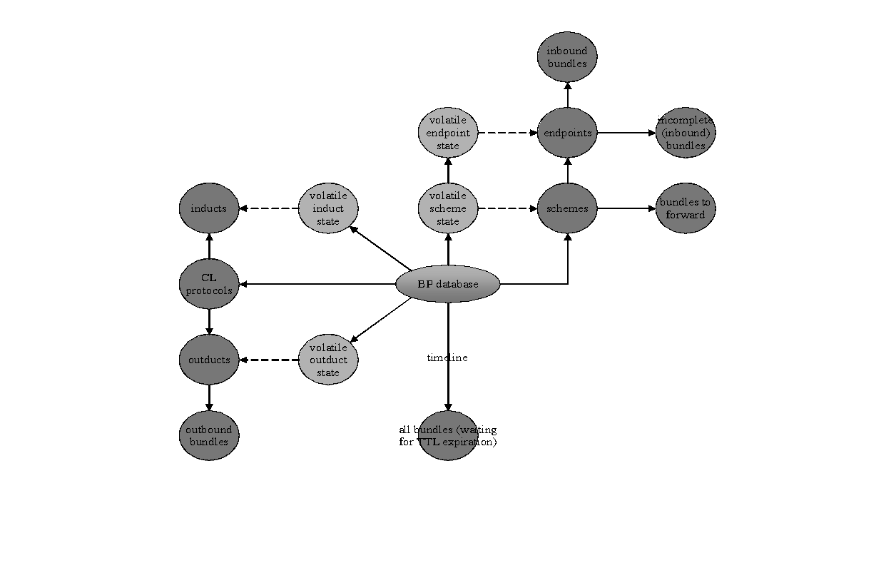
Figure 8: Bundle protocol database
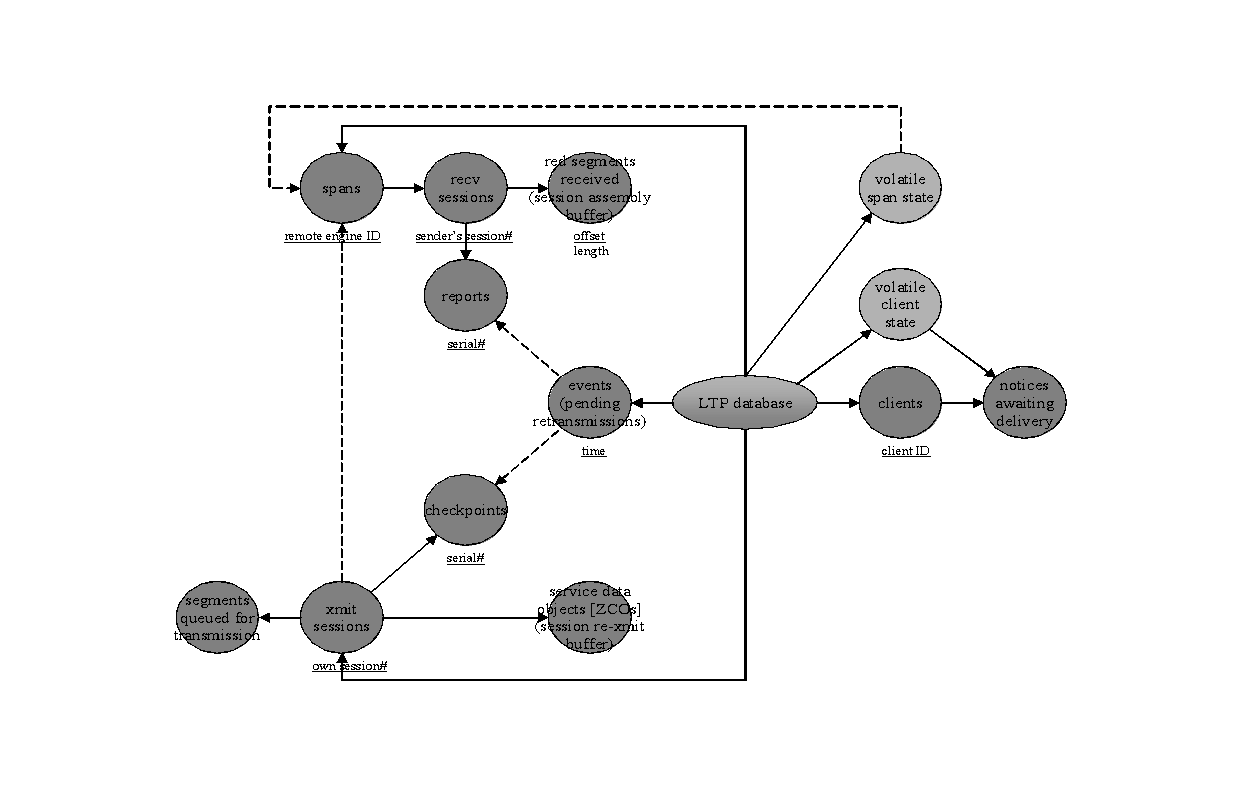
Figure 9: Licklider transmission protocol database
Control and data flow
Bundle Protocol

Figure 10 BP forwarder

Figure 11 BP convergence layer output
LTP

Figure 12 LTP transmission metering
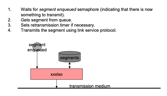
Figure 13 LTP link service output
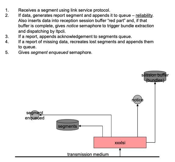
Figure 14 LTP link service input
Contact Graph Routing (CGR)
CGR is a dynamic routing system that computes routes through a time-varying topology of scheduled communication contacts in a DTN network. It is designed to support operations in a space network based on DTN, but it also could be used in terrestrial applications where operation according to a predefined schedule is preferable to opportunistic communication, as in a low-power sensor network.
The basic strategy of CGR is to take advantage of the fact that, since communication operations are planned in detail, the communication routes between any pair of "bundle agents" in a population of nodes that have all been informed of one another's plans can be inferred from those plans rather than discovered via dialogue (which is impractical over long-one-way-light-time space links).
Contact Plan Messages
CGR relies on accurate contact plan information provided in the form of contact plan messages that currently are only read from ionrc files and processed by ionadmin, which retains them in a non-volatile contact plan in the RFX database, in ION's SDR data store.
Contact plan messages are of two types: contact messages and range messages.
Each contact message has the following content:
- The starting UTC time of the interval to which the message pertains.
- The stop time of this interval, again in UTC.
- The Transmitting node number.
- The Receiving node number.
- The planned rate of transmission from node A to node B over this interval, in bytes per second.
Each range message has the following content:
- The starting UTC time of the interval to which the message pertains.
- The stop time of this interval, again in UTC.
- Node number A.
- Node number B.
- The anticipated distance between A and B over this interval, in light seconds.
Note that range messages may be used to declare that the "distance" in light seconds between nodes A and B is different in the B🡪A direction from the distance in the A🡪B direction. While direct radio communication between A and B will not be subject to such asymmetry, it's possible for connectivity established using other convergence-layer technologies to take different physical paths in different directions, with different signal propagation delays.
Routing Tables
Each node uses Range and Contact messages in the contact plan to build a \"routing table\" data structure.
The routing table constructed locally by each node in the network is a list of entry node lists, one route list for every other node D in the network that is cited in any Contact or Range in the contact plan. Entry node lists are computed as they are needed, and the maximum number of entry node lists resident at a given time is the number of nodes that are cited in any Contacts or Ranges in the contact plan. Each entry in the entry node list for node D is a list of the neighbors of local node X; included with each entry of the entry node list is a list one or more routes to D through the indicated neighbor, termed a route list.
Each route in the route list for node D identifies a path to destination node D, from the local node, that begins with transmission to one of the local node's neighbors in the network-- the initial receiving node for the route, termed the route's entry node.
For any given route, the contact from the local node to the entry node constitutes the initial transmission segment of the end-to-end path to the destination node. Additionally noted in each route object are all of the other contacts that constitute the remaining segments of the route's end-to-end path.
Each route object also notes the forwarding cost for a bundle that is forwarded along this route. In this version of ION, CGR is configured to deliver bundles as early as possible, so best-case final delivery time is used as the cost of a route. Other metrics might be substituted for final delivery time in other CGR implementations. NOTE, however, that if different metrics are used at different nodes along a bundle's end-to-end path it becomes impossible to prevent routing loops that can result in non-delivery of the data.
Finally, each route object also notes the route's termination time, the time after which the route will become moot due to the termination of the earliest-ending contact in the route.
Key Concepts
Expiration time
Every bundle transmitted via DTN has a time-to-live (TTL), the length of time after which the bundle is subject to destruction if it has not yet been delivered to its destination. The expiration time of a bundle is computed as its creation time plus its TTL. When computing the next-hop destination for a bundle that the local bundle agent is required to forward, there is no point in selecting a route that can\'t get the bundle to its final destination prior to the bundle's expiration time.
OWLT margin
One-way light time (OWLT) -- that is, distance -- is obviously a factor in delivering a bundle to a node prior to a given time. OWLT can actually change during the time a bundle is en route, but route computation becomes intractably complex if we can\'t assume an OWLT \"safety margin\" -- a maximum delta by which OWLT between any pair of nodes can change during the time a bundle is in transit between them.
We assume that the maximum rate of change in distance between any two nodes in the network is about 150,000 miles per hour, which is about 40 miles per second. (This was the speed of the Helios spacecraft, the fastest man-made object launched to date.)
At this speed, the distance between any two nodes that are initially separated by a distance of N light seconds will increase by a maximum of 80 miles per second of transit (in the event that they are moving in opposite directions). This will result in data arrival no later than roughly (N + 2Q) seconds after transmission -- where the "OWLT margin" value Q is (40 * N) divided by 186,000 -- rather than just N seconds after transmission as would be the case if the two nodes were stationary relative to each other. When computing the expected time of arrival of a transmitted bundle we simply use N + 2Q, the most pessimistic case, as the anticipated total in-transit time.
Capacity
The capacity of a contact is the product of its data transmission rate (in bytes per second) and its duration (stop time minus start time, in seconds).
Estimated capacity consumption
The size of a bundle is the sum of its payload size and its header size5, but bundle size is not the only lien on the capacity of a contact. The total estimated volume consumption (or "EVC") for a bundle is the sum of the sizes of the bundle's payload and header and the estimated convergence-layer overhead. For a bundle whose header is of size M and whose payload is of size N, the estimated convergence-layer overhead is defined as 3% of (M+N), or 100 bytes, whichever is larger.
Residual capacity
The residual capacity of a given contact between the local node and one of its neighbors, as computed for a given bundle, is the sum of the capacities of that contact and all prior scheduled contacts between the local node and that neighbor, less the sum of the ECCs of all bundles with priority equal to or higher than the priority of the subject bundle that are currently queued on the outduct for transmission to that neighbor.
Excluded neighbors
A neighboring node C that refuses custody of a bundle destined for some remote node D is termed an excluded neighbor for (that is, with respect to computing routes to) D. So long as C remains an excluded neighbor for D, no bundles destined for D will be forwarded to C -- except that occasionally (once per lapse of the RTT between the local node and C) a custodial bundle destined for D will be forwarded to C as a "probe bundle". C ceases to be an excluded neighbor for D as soon as it accepts custody of a bundle destined for D.
Critical bundles
A Critical bundle is one that absolutely has got to reach its destination and, moreover, has got to reach that destination as soon as is physically possible6.
For an ordinary non-Critical bundle, the CGR dynamic route computation algorithm uses the routing table to select a single neighboring node to forward the bundle through. It is possible, though, that due to some unforeseen delay the selected neighbor may prove to be a sub-optimal forwarder: the bundle might arrive later than it would have if another neighbor had been selected, or it might not even arrive at all.
For Critical bundles, the CGR dynamic route computation algorithm causes the bundle to be inserted into the outbound transmission queues for transmission to all neighboring nodes that can plausibly forward the bundle to its final destination. The bundle is therefore guaranteed to travel over the most successful route, as well as over all other plausible routes. Note that this may result in multiple copies of a Critical bundle arriving at the final destination.
Dynamic Route Selection Algorithm
Given a bundle whose destination is node D, we proceed as follows.
First, if no contacts in the contact plan identify transmission to node D, then we cannot use CGR to find a route for this bundle; CGR route selection is abandoned.
Next, if the contact plan has been modified in any way since routes were computed for any nodes, we discard all routes for all nodes and authorize route recomputation. (The contact plan changes may have invalidated any or all of those earlier computations.)
We create an empty list of Proximate Nodes (network neighbors) to send the bundle to.
We create a list of Excluded Nodes, i.e., nodes through which we will not compute a route for this bundle. The list of Excluded Nodes is initially populated with:
- the node from which the bundle was directly received (so that we avoid cycling the bundle between that node and the local node) -- unless the Dynamic Route Selection Algorithm is being re-applied due to custody refusal as discussed later;
- all excluded neighbors for the bundle's final destination node.
If all routes computed for node D have been discarded due to contact plan modification, then we must compute a new list of all routes from the local node to D. To do so:
- We construct an abstract contact graph, a directed acyclic graph whose root is a notional contact from the local node to itself and whose other vertices are all other contacts representing transmission "from" some node such that a contact "to" that node already exists in the graph, excluding contacts representing transmission "to" some node such that a contact "from" that node already exists in the graph. A terminal vertex is also included in the graph, constituting a notional contact from node D to itself.
-
We perform several Dijkstra searches within this graph, one search for each of the local node's neighbors. On each search we find the lowest-cost route that begins at the root of the graph and ends at the terminal vertex. Each time a route is computed, we add it to the list of routes for that route's entry node and then remove from further consideration all contacts from the local node to the entry node of that route.
-
The lowest-cost route computed during a search is the one that is found to have the earliest best-case delivery time, where the best-case delivery time characterizing a route is given by the time at which a bundle would arrive at node D if transmitted at the earliest possible moment of the last contact in the route prior to the terminal vertex.
- Any contact whose end time is before the earliest possible time that the bundle could arrive at the contact's sending node is ignored.
- The earliest possible arrival time for the bundle on a given contact is pessimistically computed as the sum of the bundle's earliest possible transmission time plus the range in light seconds from the contact's sending node to its receiving node, plus the applicable one-way light time margin.
- The earliest possible transmission time for the bundle on a given contact is the start time of the contact or bundle's earliest possible arrival time at the contact's sending node, whichever is later.
- If node D's list of entry nodes (route lists) is still empty, then we cannot use CGR to find a route for this bundle; CGR route selection is abandoned.
We next examine all of the routes that are currently computed for transmission of bundles to node D.
- Any route whose termination time is in the past is deleted from the list, and all contacts in that route whose termination time is in the past are also deleted. But we then run another Dijkstra search to compute the best route through the affected entry node given the remaining contacts; if this search finds a route, the new route is inserted into the appropriate location in the list.
- Any route whose best-case final delivery time is after the bundle's expiration time is ignored, as is any route whose entry node is in the list of Excluded Nodes. Loopback routes are also ignored unless the local node is the bundle's final destination.
- For each route, the aggregate radiation time for this bundle on this route is computed by summing the product of payload size and contact transmission rate over all contacts in the route. Any route for which the sum of best-case delivery time and aggregate radiation time is after the bundle's expiration time is ignored.
For each route that is not ignored, the route's entry node is added to the list of Proximate Nodes for this bundle. Associated with the entry node number in this list entry are the best-case final delivery time of the route, the total number of "hops" in the route's end-to-end path, and the forfeit time for transmission to this node. Forfeit time is the route's termination time, the time by which the bundle must have been transmitted to this node in order to have any chance of being forwarded on this route.
If, at the end of this procedure, the Proximate Nodes list is empty, then we have been unable to use CGR to find a route for this bundle; CGR route selection is abandoned.
Otherwise:
- If the bundle is flagged as a critical bundle, then a cloned copy of this bundle is enqueued for transmission to every node in the Proximate Nodes list.
-
Otherwise, the bundle is enqueued for transmission on the outduct to the most preferred neighbor in the Proximate Nodes list:
-
If one of the nodes in this list is associated with a best-case delivery time that is earlier than that of all other nodes in the list, then it is the most preferred neighbor.
- Otherwise, if one of the nodes with the earliest best-case delivery time is associated with a smaller hop count than every other node with the same best-case delivery time, then it is the most preferred neighbor.
- Otherwise, the node with the smallest node number among all nodes with the earliest best-case delivery time and smallest hop count is arbitrarily chosen as the most preferred neighbor.
Exception Handling
Conveyance of a bundle from source to destination through a DTN can fail in a number of ways, many of which are best addressed by means of the Delivery Assurance mechanisms described earlier. Failures in Contact Graph Routing, specifically, occur when the expectations on which routing decisions are based prove to be false. These failures of information fall into two general categories: contact failure and custody refusal.
Contact Failure
A scheduled contact between some node and its neighbor on the end-to-end route may be initiated later than the originally scheduled start time, or be terminated earlier than the originally scheduled stop time, or be canceled altogether. Alternatively, the available capacity for a contact might be overestimated due to, for example, diminished link quality resulting in unexpectedly heavy retransmission at the convergence layer. In each of these cases, the anticipated transmission of a given bundle during the affected contact may not occur as planned: the bundle might expire before the contact's start time, or the contact's stop time might be reached before the bundle has been transmitted.
For a non-Critical bundle, we handle this sort of failure by means of a timeout: if the bundle is not transmitted prior to the forfeit time for the selected Proximate Node, then the bundle is removed from its outbound transmission queue and the Dynamic Route Computation Algorithm is re-applied to the bundle so that an alternate route can be computed.
Custody refusal
A node that receives a bundle may find it impossible to forward it, for any of several reasons: it may not have enough storage capacity to hold the bundle, it may be unable to compute a forward route (static, dynamic, or default) for the bundle, etc. Such bundles are simply discarded, but discarding any such bundle that is marked for custody transfer will cause a custody refusal signal to be returned to the bundle's current custodian.
When the affected bundle is non-Critical, the node that receives the custody refusal re-applies the Dynamic Route Computation Algorithm to the bundle so that an alternate route can be computed -- except that in this event the node from which the bundle was originally directly received is omitted from the initial list of Excluded Nodes. This enables a bundle that has reached a dead end in the routing tree to be sent back to a point at which an altogether different branch may be selected.
For a Critical bundle no mitigation of either sort of failure is required or indeed possible: the bundle has already been queued for transmission on all plausible routes, so no mechanism that entails re-application of CGR's Dynamic Route Computation Algorithm could improve its prospects for successful delivery to the final destination. However, in some environments it may be advisable to re-apply the Dynamic Route Computation Algorithm to all Critical bundles that are still in local custody whenever a new Contact is added to the contact graph: the new contact may open an additional forwarding opportunity for one or more of those bundles.
Remarks
The CGR routing procedures respond dynamically to the changes in network topology that the nodes are able know about, i.e., those changes that are subject to mission operations control and are known in advance rather than discovered in real time. This dynamic responsiveness in route computation should be significantly more effective and less expensive than static routing, increasing total data return while at the same time reducing mission operations cost and risk.
Note that the non-Critical forwarding load across multiple parallel paths should be balanced automatically:
- Initially all traffic will be forwarded to the node(s) on what is computed to be the best path from source to destination.
- At some point, however, a node on that preferred path may have so much outbound traffic queued up that no contacts scheduled within bundles' lifetimes have any residual capacity. This can cause forwarding to fail, resulting in custody refusal.
- Custody refusal causes the refusing node to be temporarily added to the current custodian's excluded neighbors list for the affected final destination node. If the refusing node is the only one on the path to the destination, then the custodian may end up sending the bundle back to its upstream neighbor. Moreover, that custodian node too may begin refusing custody of bundles subsequently sent to it, since it can no longer compute a forwarding path.
- The upstream propagation of custody refusals directs bundles over alternate paths that would otherwise be considered suboptimal, balancing the queuing load across the parallel paths.
- Eventually, transmission and/or bundle expiration at the oversubscribed node relieves queue pressure at that node and enables acceptance of custody of a "probe" bundle from the upstream node. This eventually returns the routing fabric to its original configuration.
Although the route computation procedures are relatively complex they are not computationally difficult. The impact on computation resources at the vehicles should be modest.
LTP Timeout Intervals
Suppose we've got Earth ground station ES that is currently in view of Mars but will be rotating out of view ("Mars-set") at some time T1 and rotating back into view ("Mars-rise") at time T3. Suppose we've also got Mars orbiter MS that is currently out of the shadow of Mars but will move behind Mars at time T2, emerging at time T4. Let's also suppose that ES and MS are 4 light-minutes apart (Mars is at its closest approach to Earth). Finally, for simplicity, let's suppose that both ES and MS want to be communicating at every possible moment (maximum link utilization) but never want to waste any electricity.
Neither ES nor MS wants to be wasting power on either transmitting or receiving at a time when either Earth or Mars will block the signal.
ES will therefore stop transmitting at either T1 or (T2 - 4 minutes), whichever is earlier; call this time Tet0. It will stop receiving -- that is, power off the receiver -- at either T1 or (T2 + 4 minutes), whichever is earlier; call this time Ter0. It will resume transmitting at either T3 or (T4 - 4 minutes), whichever is late, and it will resume reception at either T3 or (T4 + 4 minutes), whichever is later; call these times Tet1 and Ter1.
Similarly, MS will stop transmitting at either T2 or (T1 - 4 minutes), whichever is earlier; call this time Tmt0. It will stop receiving -- that is, power off the receiver -- at either T2 or (T1 + 4 minutes), whichever is earlier; call this time Tmr0. It will resume transmitting at either T4 or (T3 - 4 minutes), whichever is later, and it will resume reception at either T4 or (T3 + 4 minutes), whichever is later; call these times Tmt1 and Tmr1.
By making sure that we don't transmit when the signal would be blocked, we guarantee that anything that is transmitted will arrive at a time when it can be received. Any reception failure is due to data corruption en route.
So the moment of transmission of an acknowledgment to any message is always equal to the moment the original message was sent plus some imputed outbound queuing delay QO1 at the sending node, plus 4 minutes, plus some imputed inbound and outbound queuing delay QI1 + QO2 at the receiving node. The nominally expected moment of reception of this acknowledgment is that moment of transmission plus 4 minutes, plus some imputed inbound queuing delay QI2 at the original sending node. That is, the timeout interval is 8 minutes + QO1 + QI1 + QO2 + QO2 -- unless this moment of acknowledgement transmission is during an interval when the receiving node is not transmitting, for whatever reason. In this latter case, we want to suspend the acknowledgment timer during any interval in which we know the remote node will not be transmitting. More precisely, we want to add to the timeout interval the time difference between the moment of message arrival and the earliest moment at which the acknowledgment could be sent, i.e., the moment at which transmission is resumed7.
So the timeout interval Z computed at ES for a message sent to MS at time TX is given by:
This can actually be computed in advance (at time TX) if T1, T2, T3, and T4 are known and are exposed to the protocol engine.
If they are not exposed, then Z must initially be estimated to be (2 * the one-way light time) + QI + QO. The timer for Z must be dynamically suspended at time Tmt0 in response to a state change as noted by ltpclock. Finally, the timer must be resumed at time Tmt1 (in response to another state change as noted by ltpclock), at which moment the correct value for Z can be computed.
CFDP
The ION implementation of CFDP is very simple, because only Class-1 (Unacknowledged) functionality is implemented: the store-and-forward routing performed by Bundle Protocol makes the CFDP Extended Procedures unnecessary and the inter-node reliability provided by the CL protocol underneath BP -- in particular, by LTP -- makes the CFDP Acknowledged Procedures unnecessary. All that CFDP is required to do is segment and reassemble files, interact with the underlying Unitdata Transfer layer -- BP/LTP -- to effect the transmission and reception of file data segments, and handle CFDP metadata including filestore requests. CFDP-ION does all this, including support for cancellation of a file transfer transaction by cancellation of the transmission of the bundles encapsulating the transaction's protocol data units.
Note that all CFDP data transmission is "by reference", via the ZCO system, rather than "by value": the retransmission buffer for a bundle containing CFDP file data is an extent of the original file itself, not a copy retained in the ION database, and data received in bundles containing CFDP PDU is written immediately to the appropriate location in the reconstituted file rather than stored in the ION database. This minimizes the space needed for the database. In general, file transmission via CFDP is the most memory-efficient way to use ION in flight operations.
Figure 15 A CFDP-ION entity
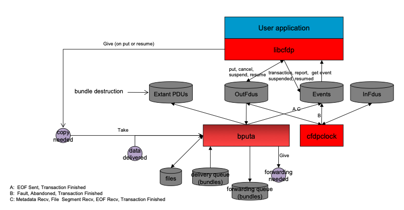
List data structures (lyst, sdrlist, smlist)
Figure 16 ION list data structures
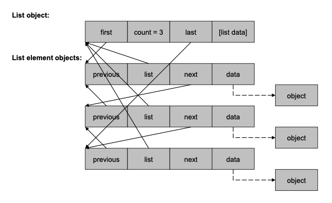
PSM Partition Structure
Figure 17 psm partition structure

PSM and SDR Block Structures
Figure 18 psm and sdr block structures
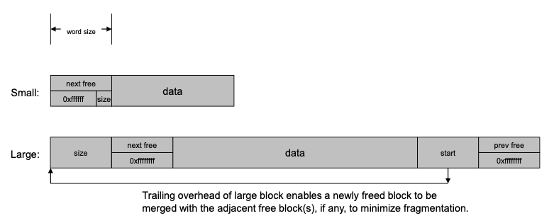
SDR Heap Structure
Figure 19 sdr heap structure
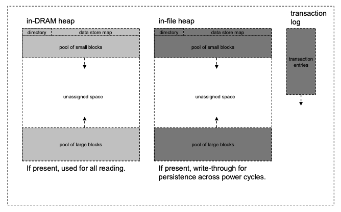
Operation
The ION source distribution contains a README.TXT file with details on building ION from source. For installations starts with the open source distribution ION-DTN, using the standard sequence of
-
./configure
-
Note: the user needs to clear all errors reported by the configure script before proceeding. The distribution contains a default "Makefile" at the top level of the distribution for developer use. The configure script must complete successfully to produce an updated Makefile.
- make
- sudo make install
will build ION and install it under /usr/local.
Users building from a clone of the repository need to use the command
- autoreconf -fi
before starting the installation.
The "Build" instructions shown in the following sections for each package are the instructions for building each package individually, for ION development purposes. The default installation target for the individual package build commands is /opt.
One compile-time option is applicable to all ION packages: the platform selection parameters --DVXWORKS and --DRTEMS affect the manner in which most task instantiation functions are compiled. For VXWORKS and RTEMS, these functions are compiled as library functions that must be identified by name in the platform's symbol table, while for Unix-like platforms they are compiled as main()functions.
Interplanetary Communication Infrastructure (ICI)
Compile-time options
Declaring values for the following variables, by setting parameters that are provided to the C compiler (for example, --DFSWSOURCE or --DSM_SEMBASEKEY=0xff13), will alter the functionality of ION as noted below.
PRIVATE_SYMTAB
This option causes ION to be built for VxWorks 5.4 or RTEMS with reliance on a small private local symbol table that is accessed by means of a function named sm_FindFunction. Both the table and the function definition are, by default, provided by the symtab.c source file, which is automatically included within the platform_sm.c source when this option is set. The table provides the address of the top-level function to be executed when a task for the indicated symbol (name) is to be spawned, together with the priority at which that task is to execute and the amount of stack space to be allocated to that task.
PRIVATE_SYMTAB is defined by default for RTEMS but not for VxWorks 5.4.
Absent this option, ION on VxWorks 5.4 must successfully execute the VxWorks symFindByName function in order to spawn a new task. For this purpose the entire VxWorks symbol table for the compiled image must be included in the image, and task priority and stack space allocation must be explicitly specified when tasks are spawned.
FSWLOGGER
This option causes the standard ION logging function, which simply writes all ION status messages to a file named ion.log in the current working directory, to be replaced (by #include) with code in the source file fswlogger.c. A file of this name must be in the inclusion path for the compiler, as defined by --Ixxxx compiler option parameters.
FSWCLOCK
This option causes the invocation of the standard time function within getUTCTime (in ion.c) to be replaced (by #include) with code in the source file fswutc.c, which might for example invoke a mission-specific function to read a value from the spacecraft clock. A file of this name must be in the inclusion path for the compiler.
FSWWDNAME
This option causes the invocation of the standard getcwd function within cfdpInit (in libcfdpP.c) to be replaced (by #include) with code in the source file wdname.c, which must in some way cause the mission-specific value of the current working directory name to be copied into cfdpdbBuf.workingDirectoryName. A file of this name must be in the inclusion path for the compiler.
FSWSYMTAB
If the PRIVATE_SYMTAB option is also set, then the FSWSYMTAB option causes the code in source file mysymtab.c to be included in platform_sm.c in place of the default symbol table access implementation in symtab.c. A file named mysymtab.c must be in the inclusion path for the compiler.
FSWSOURCE
This option simply causes FSWLOGGER, FSWCLOCK, FSWWDNAME, and FSWSYMTAB all to be set.
GDSLOGGER
This option causes the standard ION logging function, which simply writes all ION status messages to a file named ion.log in the current working directory, to be replaced (by #include) with code in the source file gdslogger.c. A file of this name must be in the inclusion path for the compiler, as defined by --Ixxxx compiler option parameters.
GDSSOURCE
This option simply causes GDSLOGGER to be set.
ION_OPS_ALLOC=*xx*
This option specifies the percentage of the total non-volatile storage space allocated to ION that is reserved for protocol operational state information, i.e., is not available for the storage of bundles or LTP segments. The default value is 20.
ION_SDR_MARGIN=*xx*
This option specifies the percentage of the total non-volatile storage space allocated to ION that is reserved simply as margin, for contingency use. The default value is 20.
The sum of ION_OPS_ALLOC and ION_SDR_MARGIN defines the amount of non-volatile storage space that is sequestered at the time ION operations are initiated: for purposes of congestion forecasting and prevention of resource oversubscription, this sum is subtracted from the total size of the SDR "heap" to determine the maximum volume of space available for bundles and LTP segments. Data reception and origination activities fail whenever they would cause the total amount of data store space occupied by bundles and segments to exceed this limit.
USING_SDR_POINTERS
This is an optimization option for the SDR non-volatile data management system: when set, it enables the value of any variable in the SDR data store to be accessed directly by means of a pointer into the dynamic memory that is used as the data store storage medium, rather than by reading the variable into a location in local stack memory. Note that this option must not be enabled if the data store is configured for file storage only, i.e., if the SDR_IN_DRAM flag was set to zero at the time the data store was created by calling sdr_load_profile. See the ionconfig(5) man page in Appendix A for more information.
NO_SDR_TRACE
This option causes non-volatile storage utilization tracing functions to be omitted from ION when the SDR system is built. It disables a useful debugging option but reduces the size of the executable software.
NO_PSM_TRACE
This option causes memory utilization tracing functions to be omitted from ION when the PSM system is built. It disables a useful debugging option but reduces the size of the executable software.
IN_FLIGHT
This option controls the behavior of ION when an unrecoverable error is encountered.
If it is set, then the status message "Unrecoverable SDR error" is logged and the SDR non-volatile storage management system is globally disabled: the current database access transaction is ended and (provided transaction reversibility is enabled) rolled back, and all ION tasks terminate.
Otherwise, the ION task that encountered the error is simply aborted, causing a core dump to be produced to support debugging.
SM_SEMKEY=0x*XXXX*
This option overrides the default value (0xee01) of the identifying "key" used in creating and locating the global ION shared-memory system mutex.
SVR4_SHM
This option causes ION to be built using svr4 shared memory as the pervasive shared-memory management mechanism. svr4 shared memory is selected by default when ION is built for any platform other than MinGW, VxWorks 5.4, or RTEMS. (For these latter operating systems all memory is shared anyway, due to the absence of a protected-memory mode.)
POSIX1B_SEMAPHORES
This option causes ION to be built using POSIX semaphores as the pervasive semaphore mechanism. POSIX semaphores are selected by default when ION is built for RTEMS but are otherwise not used or supported; this option enables the default to be overridden.
SVR4_SEMAPHORES
This option causes ION to be built using svr4 semaphores as the pervasive semaphore mechanism. svr4 semaphores are selected by default when ION is built for any platform other than MinGW (for which Windows event objects are used), VxWorks 5.4 (for which VxWorks native semaphores are the default choice), or RTEMS (for which POSIX semaphores are the default choice).
SM_SEMBASEKEY=0x*XXXX*
This option overrides the default value (0xee02) of the identifying "key" used in creating and locating the global ION shared-memory semaphore database, in the event that svr4 semaphores are used.
SEMMNI=*xxx*
This option declares to ION the total number of svr4 semaphore sets provided by the operating system, in the event that svr4 semaphores are used. It overrides the default value, which is 10 for Cygwin and 128 otherwise. (Changing this value typically entails rebuilding the O/S kernel.)
SEMMSL=*xxx*
This option declares to ION the maximum number of semaphores in each svr4 semaphore set, in the event that svr4 semaphores are used. It overrides the default value, which is 6 for Cygwin and 250 otherwise. (Changing this value typically entails rebuilding the O/S kernel.)
SEMMNS=*xxx*
This option declares to ION the total number of svr4 semaphores that the operating system can support; the maximum possible value is SEMMNI x SEMMSL. It overrides the default value, which is 60 for Cygwin and 32000 otherwise. (Changing this value typically entails rebuilding the O/S kernel.)
ION_NO_DNS
This option causes the implementation of a number of Internet socket I/O operations to be omitted for ION. This prevents ION software from being able to operate over Internet connections, but it prevents link errors when ION is loaded on a spacecraft where the operating system does not include support for these functions.
ERRMSGS_BUFSIZE=*xxxx*
This option set the size of the buffer in which ION status messages are constructed prior to logging. The default value is 4 KB.
SPACE_ORDER=*x*
This option declares the word size of the computer on which the compiled ION software will be running: it is the base-2 log of the number of bytes in an address. The default value is 2, i.e., the size of an address is 2^2^ = 4 bytes. For a 64-bit machine, SPACE_ORDER must be declared to be 3, i.e., the size of an address is 2^3^ = 8 bytes.
NO_SDRMGT
This option enables the SDR system to be used as a data access transaction system only, without doing any dynamic management of non-volatile data. With the NO_SDRMGT option set, the SDR system library can (and in fact must) be built from the sdrxn.c source file alone.
DOS_PATH_DELIMITER
This option causes ION_PATH_DELIMITER to be set to '\' (backslash), for use in construction path names. The default value of ION_PATH_DELIMITER is '/' (forward slash, as is used in Unix-like operating systems).
Build
To build ICI for a given deployment platform:
-
Decide where you want ION's executables, libraries, header files, etc. to be installed. The ION makefiles all install their build products to subdirectories (named bin, lib, include, man, man/man1, man/man3, man/man5) of an ION root directory, which by default is the directory named /opt. If you wish to use the default build configuration, be sure that the default directories (/opt/bin, etc.) exist; if not, select another ION root directory name -- this document will refer to it as $OPT -- and create the subdirectories as needed. In any case, make sure that you have read, write, and execute permission for all of the ION installation directories and that:
-
The directory /$OPT/bin is in your execution path.
- The directory /$OPT/lib is in your $LD_LOADLIB_PATH.
-
Edit the Makefile in ion/ici:
-
Make sure PLATFORMS is set to the appropriate platform name, e.g., x86-redhat, sparc-sol9, etc.
-
Set OPT to the directory where you want to install the ici packages you build, if other than "/opt" (for example: /usr/local).
-
Then:
Configure
Three types of files are used to provide the information needed to perform global configuration of the ION protocol stack: the ION system configuration (or ionconfig) file, the ION administration command (ionrc) file, and the ION security configuration (ionsecrc) file. For details, see the man pages for ionconfig(5), ionrc(5), and ionsecrc(5) in Appendix A.
Normally the instantiation of ION on a given computer establishes a single ION node on that computer, for which hard-coded values of wmKey and sdrName (see ionconfig(5)) are used in common by all executables to assure that all elements of the system operate within the same state space. For some purposes, however, it may be desirable to establish multiple ION nodes on a single workstation. (For example, constructing an entire self-contained DTN network on a single machine may simplify some kinds of regression testing.) ION supports this configuration option as follows:
- Multi-node operation on a given computer is enabled if and only if the environment variable ION_NODE_LIST_DIR is defined in the environment of every participating ION process. Moreover, the value assigned to this variable must be the same text string in the environments of all participating ION processes. That value must be the name (preferably, fully qualified) of the directory in which the ION multi-node database file "ion_nodes" will reside.
- The definition of ION_NODE_LIST_DIR makes it possible to establish up to one ION node per directory rather than just one ION node on the computer. When ionadmin is used to establish a node, the ionInitialize() function will get that node's wmKey and sdrName from the .ionconfig file, use them to allocate working memory and create the SDR database, and then write a line to the ion_nodes file noting the nodeNbr, wmKey, sdrName, and wdName for the node it just initialized. wdName is the current working directory in which ionadmin was running at the time ionInitialize()is called; it is the directory within which the node resides.
- This makes it easy to connect all the node\'s daemon processes -- running within the same current working directory -- to the correct working memory partition and SDR database: the ionAttach() function simply searches the ion_nodes file for a line whose wdName matches the current working directory of the process that is trying to attach, then uses that line\'s wmKey and sdrName to link up.
- It is also possible to initiate a process from within a directory other than the one in which the node resides. To do so, define the additional environment variable ION_NODE_WDNAME in the shell from which the new process is to be initiated. When ionAttach() is called it will first try to get \"current working directory\" (for ION attachment purposes only) from that environment variable; only if ION_NODE_WDNAME is undefined will it use the actual cwd that it gets from calling igetcwd().
- When running multiple ION instances, the first ION instance must have the largest sdr working memory specified by
sdrWmSizeor default. If any later ION instance launched withsdrWmSizeexceeding the first ION instance, it will result in crash upon launch. It is further recommended that all ION instances running simultaneously on a single host should set theirsdrWmSizethe same.
Run
The executable programs used in operation of the ici component of ION include:
- The ionadmin system configuration utility and ionsecadmin security configuration utility, invoked at node startup time and as needed thereafter.
- The rfxclock background daemon, which affects scheduled network configuration events.
- The sdrmend system repair utility, invoked as needed.
- The sdrwatch and psmwatch utilities for resource utilization monitoring, invoked as needed.
Each time it is executed, ionadmin computes a new congestion forecast and, if a congestion collapse is predicted, invokes the node's congestion alarm script (if any). ionadmin also establishes the node number for the local node and starts/stops the rfxclock task, among other functions. For further details, see the man pages for ionadmin(1), ionsecadmin(1), rfxclock(1), sdrmend(1), sdrwatch(1), and psmwatch(1) in Appendix A.
Test
Six test executables are provided to support testing and debugging of the ICI component of ION:
- The file2sdr and sdr2file programs exercise the SDR system.
- The psmshell program exercises the PSM system.
- The file2sm, sm2file, and smlistsh programs exercise the shared-memory linked list system.
For details, see the man pages for file2sdr(1), sdr2file(1), psmshell(1), file2sm(1), sm2file(1), and smlistsh(1) in Appendix A.
Licklider Transmission Protocol (LTP)
Build
To build LTP:
- Make sure that the "ici" component of ION has been built for the platform on which you plan to run LTP.
-
Edit the Makefile in ion/ltp:
-
As for ici, make sure PLATFORMS is set to the name of the platform on which you plan to run LTP.
-
Set OPT to the directory containing the bin, lib, include, etc. directories where the ici package is installed (for example: /usr/local).
-
Then:
Configure
The LTP administration command (ltprc) file provides the information needed to configure LTP on a given ION node. For details, see the man page for ltprc(5) in Appendix A.
Run
The executable programs used in operation of the ltp component of ION include:
- The ltpadmin protocol configuration utility, invoked at node startup time and as needed thereafter.
- The ltpclock background daemon, which affects scheduled LTP events such as segment retransmissions.
- The ltpmeter block management daemon, which segments blocks and effects LTP flow control.
- The udplsi and udplso link service input and output tasks, which handle transmission of LTP segments encapsulated in UDP datagrams (mainly for testing purposes).
ltpadmin starts/stops the ltpclock and ltpmeter tasks and, as mandated by configuration, the udplsi and udplso tasks.
For details, see the man pages for ltpadmin(1), ltpclock(1), ltpmeter(1), udplsi(1), and udplso(1) in Appendix A.
Test
Two test executables are provided to support testing and debugging of the LTP component of ION:
- ltpdriver is a continuous source of LTP segments.
- ltpcounter is an LTP block receiver that counts blocks as they arrive.
For details, see the man pages for ltpdriver(1) and ltpcounter(1) in Appendix A.
Bundle Streaming Service Protocol (BSSP)
Build
To build BSSP:
- Make sure that the "ici" component of ION has been built for the platform on which you plan to run BSSP.
-
Edit the Makefile in ion/bssp:
-
As for ici, make sure PLATFORMS is set to the name of the platform on which you plan to run BSSP.
-
Set OPT to the directory containing the bin, lib, include, etc. directories where the ici package is installed (for example: /usr/local).
-
Then:
Configure
The BSSP administration command (bssprc) file provides the information needed to configure BSSP on a given ION node. For details, see the man page for bssprc(5) in Appendix A.
The bssprc file has a command option specifying the max_block_size. This is to prevent retransmission inefficiency when the blocks size of a stream data is too large. The unit of retransmission for BSSP is the block, so if the block size is too large, it is very expensive to the network to provide retransmission. If one needs bulk data transfer, instead of streaming, one should use BP with reliability LTP instead of using BSSP. If you are using udpbso and udpbsi as the underlying convergence layer, then the max_block_size parameter for bssprc cannot be larger than 65507 bytes, because each UDP datagram can only be as large as 65507 bytes (payload) + 20 (IP Header) + 8 (UDP Header) = 65535 byte.
Run
The executable programs used in operation of the bssp component of ION include:
- The bsspadmin protocol configuration utility, invoked at node startup time and as needed thereafter.
- The bsspclock background daemon, which affects scheduled BSSP events such as segment retransmissions.
- The udpbsi and udpbso link service input and output tasks, which handle transmission of BSSP segments encapsulated in UDP datagrams (mainly for testing purposes; in space domain, the appropriate CCSDS link layer will be used instead of UDP).
bsspadmin starts/stops the bsspclock task and, as mandated by configuration, the udpbsi and udblso tasks.
For details, see the man pages for bsspadmin(1), bsspclock(1), bsspmeter(1), udpbsi(1), and udpbso(1) in Appendix A.
Bundle Protocol (BP)
Compile-time options
Declaring values for the following variables, by setting parameters that are provided to the C compiler (for example, --DION_NOSTATS or --DBRSTERM=60), will alter the functionality of BP as noted below.
TargetFFS
Setting this option adapts BP for use with the TargetFFS flash file system on the VxWorks operating system. TargetFFS apparently locks one or more system semaphores so long as a file is kept open. When a BP task keeps a file open for a sustained interval, subsequent file system access may cause a high-priority non-BP task to attempt to lock the affected semaphore and therefore block; in this event, the priority of the BP task may automatically be elevated by the inversion safety mechanisms of VxWorks. This "priority inheritance" can result in preferential scheduling for the BP task -- which does not need it -- at the expense of normally higher-priority tasks, and can thereby introduce runtime anomalies. BP tasks should therefore close files immediately after each access when running on a VxWorks platform that uses the TargetFFS flash file system. The TargetFFS compile-time option ensures that they do so.
BRSTERM=xx
This option sets the maximum number of seconds by which the current time at the BRS server may exceed the time tag in a BRS authentication message from a client; if this interval is exceeded, the authentication message is presumed to be a replay attack and is rejected. Small values of BRSTERM are safer than large ones, but they require that clocks be more closely synchronized. The default value is 5.
ION_NOSTATS
Setting this option prevents the logging of bundle processing statistics in status messages.
KEEPALIVE_PERIOD=xx
This option sets the number of seconds between transmission of keep-alive messages over any TCP or BRS convergence-layer protocol connection. The default value is 15.
ION_BANDWIDTH_RESERVED
Setting this option overrides strict priority order in bundle transmission, which is the default. Instead, bandwidth is shared between the priority-1 and priority-0 queues on a 2:1 ratio whenever there is no priority-2 traffic.
ENABLE_BPACS
This option causes Aggregate Custody Signaling source code to be included in the build. ACS is alternative custody transfer signaling mechanism that sharply reduces the volume of custody acknowledgment traffic.
ENABLE_IMC
This option causes IPN Multicast source code to be included in the build. IMC is discussed in section 1.8.4 above.
Build
To build BP:
- Make sure that the "ici", "ltp", "dgr", and "bssp" components of ION have been built for the platform on which you plan to run BP.
-
Edit the Makefile in ion/bp:
-
As for ici, make sure PLATFORMS is set to the name of the platform on which you plan to run BP.
-
Set OPT to the directory containing the bin, lib, include, etc. directories where the ici package is installed (for example: /usr/local).
-
Then:
Configure
The BP administration command (bprc) file provides the information needed to configure generic BP on a given ION node. The IPN scheme administration command (ipnrc) file provides information that configures static and default routes for endpoints whose IDs conform to the "ipn" scheme. The DTN scheme administration command (dtn2rc) file provides information that configures static and default routes for endpoints whose IDs conform to the "dtn" scheme, as supported by the DTN2 reference implementation. For details, see the man pages for bprc(5), ipnrc(5), and dtn2rc(5) in Appendix A.
Run
The executable programs used in operation of the bp component of ION include:
- The bpadmin, ipnadmin, and dtn2admin protocol configuration utilities, invoked at node startup time and as needed thereafter.
- The bpclock background daemon, which effects scheduled BP events such as TTL expirations and which also implements rate control.
- The ipnfw and dtn2fw forwarding daemons, which compute routes for bundles addressed to "ipn"-scheme and "dtn"-scheme endpoints, respectively.
- The ipnadminep and dtn2adminep administrative endpoint daemons, which handle custody acceptances, custody refusals, and status messages.
- The bpclm background daemon, which selects convergence-layer outducts by which bundles are transmitted to neighboring nodes.
- The brsscla (server) and brsccla (client) Bundle Relay Service convergence-layer adapters.
- The tcpcli (input) TCP convergence-layer adapter, which includes convergence-layer output functionality in privately managed threads.
- The stcpcli (input) and stcpclo (output) simplified TCP convergence-layer adapters.
- The udpcli (input) and udpclo (output) UDP convergence-layer adapters.
- The ltpcli (input) and ltpclo (output) LTP convergence-layer adapters.
- The dgrcla Datagram Retransmission convergence-layer adapter.
- The bpsendfile utility, which sends a file of arbitrary size, encapsulated in a single bundle, to a specified BP endpoint.
- The bpstats utility, which prints a snapshot of currently accumulated BP processing statistics on the local node.
- The bptrace utility, which sends a bundle through the network to enable a forwarding trace based on bundle status reports.
- The lgsend and lgagent utilities, which are used for remote administration of ION nodes.
- The hmackeys utility, which can be used to create hash keys suitable for use in bundle authentication blocks and BRS convergence-layer protocol connections.
bpadmin starts/stops the bpclock task and, as mandated by configuration, the ipnfw, dtn2fw, ipnadminep, dtn2adminep, bpclm, brsscla, brsccla, tcpcli, stcpcli, stcpclo, udpcli, udpclo, ltpcli, ltpclo, and dgrcla tasks.
For details, see the man pages for bpadmin(1),ipnadmin(1), dtn2admin(1), bpclock(1), bpclm(1), ipnfw(1), dtn2fw(1), ipnadminep(1), dtn2adminep(1), brsscla(1), brsccla(1),tcpcli(1), stcpcli(1), stcpclo(1), udpcli(1), udpclo(1), ltpcli(1), ltpclo(1), dgrcla(1), bpsendfile(1), bpstats(1), bptrace(1), lgsend(1), lgagent(1), and hmackeys(1) in Appendix A.
Test
Five test executables are provided to support testing and debugging of the BP component of ION:
- bpdriver is a continuous source of bundles.
- bpcounter is a bundle receiver that counts bundles as they arrive.
- bpecho is a bundle receiver that sends an "echo" acknowledgment bundle back to bpdriver upon reception of each bundle.
- bpsource is a simple console-like application for interactively sending text strings in bundles to a specified DTN endpoint, nominally a bpsink task.
- bpsink is a simple console-like application for receiving bundles and printing their contents.
For details, see the man pages for bpdriver(1), bpcounter(1), bpecho(1), bpsource(1), and bpsink(1) in Appendix A.
Datagram Retransmission (DGR)
Build
To build DGR:
- Make sure that the "ici" component of ION has been built for the platform on which you plan to run DGR.
-
Edit the Makefile in ion/dgr:
-
As for ici, make sure PLATFORMS is set to the name of the platform on which you plan to run DGR.
-
Set OPT to the directory containing the bin, lib, include, etc. directories where the ici package is installed (for example: /usr/local).
-
Then:
Configure
No additional configuration files are required for the operation of the DGR component of ION.
Run
No runtime executables are required for the operation of the DGR component of ION.
Test
Two test executables are provided to support testing and debugging of the DGR component of ION:
- file2dgr repeatedly reads a file of text lines and sends copies of those text lines via DGR to dgr2file, which writes them to a copy of the original file.
For details, see the man pages for file2dgr(1) and dgr2file(1) in Appendix A.
Asynchronous Message Service (AMS)
Compile-time options
Note that, by default, the syntax by which AMS MIB information is presented to AMS is as documented in the "amsrc" man page. Alternatively it is possible to use an XML-based syntax as documented in the "amsxml" man page. To use the XML-based syntax instead, be sure that the "expat" XML interpretation system is installed and pass the argument "--with-expat" to "./configure" when building ION.
Defining the following macros, by setting parameters that are provided to the C compiler (for example, DAMS_INDUSTRIAL), will alter the functionality of AMS as noted below.
AMS_INDUSTRIAL
Setting this option adapts AMS to an "industrial" rather than safety-critical model for memory management. By default, the memory acquired for message transmission and reception buffers in AMS is allocated from limited ION working memory, which is fixed at ION start-up time; this limits the rate at which AMS messages may be originated and acquired. When --DAMS_INDUSTRIAL is set at compile time, the memory acquired for message transmission and reception buffers in AMS is allocated from system memory, using the familiar malloc() and free() functions; this enables much higher message traffic rates on machines with abundant system memory.
Build
To build AMS:
- Make sure that the "bp" component of ION has been built for the platform on which you plan to run AMS.
-
Edit the Makefile in ion/cfdp:
-
Just as for bp, make sure PLATFORMS is set to the name of the platform on which you plan to run AMS.
-
Set OPT to the directory containing the bin, lib, include, etc. directories where the ici package is installed (for example: /usr/local).
-
Then:
Configure
There is no central configuration of AMS; each AMS entity (configuration server, registrar, or application module) is individually configured at the time its initial MIB is loaded at startup. Note that a single MIB may be shared between multiple AMS entities without issue.
For details of MIB file syntax, see the man pages for amsrc(5) and amsxml(5) in Appendix A.
Run
The executable programs used in operation of the AMS component of ION include:
- The amsd background daemon, which serves as configuration server and/or as the registrar for a single application cell.
- The ramsgate application module, which serves as the Remote AMS gateway for a single message space.
- The amsstop utility, which terminates all AMS operation throughout a single message space.
- The amsmib utility, which announces supplementary MIB information to selected subsets of AMS entities without interrupting the operation of the message space.
For details, see the man pages for amsd(1), ramsgate(1), amsstop(1), and amsmib(1) in Appendix A.
Test
Seven test executables are provided to support testing and debugging of the AMS component of ION:
- amsbenchs is a continuous source of messages.
- amsbenchr is a message receiver that calculates bundle transmission performance statistics.
- amshello is an extremely simple AMS "hello, world" demo program -- a self-contained distributed application in a single source file of about seventy lines.
- amsshell is a simple console-like application for interactively publishing, sending, and announcing text strings in messages.
- amslog is a simple console-like application for receiving messages and piping their contents to stdout.
- amslogprt is a pipeline program that simply prints AMS message contents piped to it from amslog.
- amspubsub is a pair of functions for rudimentary testing of AMS functionality in a VxWorks environment.
For details, see the man pages for amsbenchs(1), amsbenchr(1), amshello(1), amsshell(1), amslog(1), amslogprt(1), amspub(1), and amssub(1) in Appendix A.
For further operational details of the AMS system, please see sections 4 and 5 of the AMS Programmer's Guide.
CCSDS File Delivery Protocol (CFDP)
Compile-time options
Defining the following macro, by setting a parameter that is provided to the C compiler (i.e., --DTargetFFS), will alter the functionality of CFDP as noted below.
TargetFFS
Setting this option adapts CFDP for use with the TargetFFS flash file system on the VxWorks operating system. TargetFFS apparently locks one or more system semaphores so long as a file is kept open. When a CFDP task keeps a file open for a sustained interval, subsequent file system access may cause a high-priority non-CFDP task to attempt to lock the affected semaphore and therefore block; in this event, the priority of the CFDP task may automatically be elevated by the inversion safety mechanisms of VxWorks. This "priority inheritance" can result in preferential scheduling for the CFDP task -- which does not need it -- at the expense of normally higher-priority tasks, and can thereby introduce runtime anomalies. CFDP tasks should therefore close files immediately after each access when running on a VxWorks platform that uses the TargetFFS flash file system. The TargetFFS compile-time option ensures that they do so.
Build
To build CFDP:
- Make sure that the "bp" component of ION has been built for the platform on which you plan to run CFDP.
-
Edit the Makefile in ion/cfdp:
-
Just as for bp, make sure PLATFORMS is set to the name of the platform on which you plan to run CFDP.
-
Set OPT to the directory containing the bin, lib, include, etc. directories where the ici package is installed.
-
Then:
Configure
The CFDP administration command (cfdprc) file provides the information needed to configure CFDP on a given ION node. For details, see the man page for cfdprc(5) in Appendix A.
Run
The executable programs used in operation of the CFDP component of ION include:
- The cfdpadmin protocol configuration utility, invoked at node startup time and as needed thereafter.
- The cfdpclock background daemon, which affects scheduled CFDP events such as check timer expirations. The cfdpclock task also affects CFDP transaction cancellations, by canceling the bundles encapsulating the transaction's protocol data units.
- The bputa UT-layer input/output task, which handles transmission of CFDP PDUs encapsulated in bundles.
cfdpadmin starts/stops the cfdpclock task and, as mandated by configuration, the bputa task.
For details, see the man pages for cfdpadmin(1), cfdpclock(1), and bputa(1) in Appendix A.
Test
A single executable, cfdptest, is provided to support testing and debugging of the DGR component of ION. For details, see the man page for cfdptest(1) in Appendix A.
Bundle Streaming Service (BSS)
Compile-time options
Defining the following macro, by setting a parameter that is provided to the C compiler (e.g., --DWINDOW=10000), will alter the functionality of BSS as noted below.
WINDOW=xx
Setting this option changes the maximum number of seconds by which the BSS database for a BSS application may be "rewound" for replay. The default value is 86400 seconds, which is 24 hours.
Build
To build BSS:
- Make sure that the "bp" component of ION has been built for the platform on which you plan to run BSS.
- Edit the Makefile in ion/bss:
- As for ici, make sure PLATFORMS is set to the name of the platform on which you plan to run BSS.
- Set OPT to the directory containing the bin, lib, include, etc. directories where the ici package is installed (for example: /usr/local).
- Then:
Configure
No additional configuration files are required for the operation of the BSS component of ION.
Run
No runtime executables are required for the operation of the BSS component of ION.
Test
Four test executables are provided to support testing and debugging of the BSS component of ION:
- bssdriver sends a stream of data to bsscounter for non-interactive testing.
- bssStreamingApp sends a stream of data to bssrecv for graphical, interactive testing.
For details, see the man pages for bssdriver(1), bsscounter(1), bssStreamingApp(1), and bssrecv(1) in Appendix A.
-
In ION, reliable convergence-layer protocols (where available) are by default used for every bundle. The application can instead mandate selection of "best-effort" service at the convergence layer by setting the BP_BEST_EFFORT flag in the "extended class of service flags" parameter, but this feature is an ION extension that is not supported by other BP implementations at the time of this writing. ↩
-
Note that, in all occupancy figures, ION data management accounts not only for the sizes of the payloads of all queued bundles but also for the sizes of their headers. ↩
-
Barring data loss or corruption for which the various retransmission mechanisms in ION cannot compensate. ↩
-
Note that ION may indeed block the offering of a message to the network, but this is local admission control -- assuring that the node's local buffer space for queuing outbound bundles is not oversubscribed -- rather than end-to-end flow control. It is always possible for there to be ample local buffer space yet insufficient network capacity to convey the offered data to their final destination, and vice versa. ↩
-
The minimum size of an ION bundle header is 26 bytes. Adding extension blocks (such as those that effect the Bundle Security Protocol) will increase this figure. ↩
-
In ION, all bundles are by default non-critical. The application can indicate that data should be sent in a Critical bundle by setting the BP_MINIMUM_LATENCY flag in the "extended class of service" parameter, but this feature is an ION extension that is not supported by other BP implementations at the time of this writing. ↩
-
If we wanted to be extremely accurate we could also subtract from the timeout interval the imputed inbound queuing delay QI, since inbound queuing would presumably be completed during the interval in which transmission was suspended. But since we're guessing at the queuing delays anyway, this adjustment doesn't make a lot of sense. ↩